
 Excavator
316 models
 Backhoe Loader
54 models
 Crane
68 models
 Concrete Mixer
79 models
 Wheel Loader
65 models
 Compactor / Roller
45 models
 Motor Grader
42 models

 Concrete Pump
66 models
 Skid Steer Loader
11 models


A tower crane runs on a three-phase 400 V, 50 Hz supply, and the power it asks for grows with its size. Potain’s data sheets list 18 kVA for a 4-tonne self-erecting crane and 157 kVA for a 25-tonne top-slewing crane fitted with its biggest hoist, and the supply has to hold that figure at the crane while the hoist lifts a full load.
The crane maker states what the crane needs. The site has to bring it to the mast base: an incoming supply from the electricity board or a DG set, a cable sized and protected for the run, a lockable isolator and a proper earth, all ready before erection day. This guide works through the numbers from four maker sheets, the current they mean at Indian voltage, and what IS 6521, IS 13367, IS 3043 and IS 732 ask for at the base. How the crane is built and how it lifts is explained in the tower crane guide.
What power supply does a tower crane need?
A three-phase alternating current supply at the voltage and frequency printed on the crane’s data sheet. The four Potain sheets used in this guide all ask for 400 V, plus or minus 10 percent, at 50 Hz. That is a working window of 360 to 440 V at the crane. The Evy 30-23 sheet also lists a 480 V, 60 Hz version.
Indian low-voltage supply is 415 V between phases and 240 V between a phase and neutral, the figures the Indian earthing code IS 3043:2018 uses when it describes building sites. 415 V sits inside the 360 to 440 V window, so a crane built for 400 V works on it. The catch is that the voltage has to stay inside the window at the crane’s own terminals when the hoist is pulling its highest current, and that depends on the cable and the source as much as on the nominal figure.
A single-phase supply cannot run any of these cranes. Three-phase brings its own risk: if one of the three phases drops out, a running motor can be damaged. IS 6521-1, the Indian code for the design of tower cranes, asks makers to fit single-phase preventers to protect the motors from exactly that (clause 36.3). Each Potain sheet also prints IEC 60204-32, the international standard for the electrical equipment of hoisting machines.
How much kVA does a tower crane need?
Read it off the crane’s data sheet. Makers print a “required power” figure in kVA (kilovolt-amperes, the total load the supply has to carry), and it is the number to plan the whole supply around. The table sets out four Potain cranes from a small self-erector to a 25-tonne top-slewing crane, with the motor behind each movement.
| Crane and maximum load | Hoist motor | Trolley motor | Slewing motors | Installed motor power | Required power on the sheet (full / lowest) | Current at 415 V (full / lowest) |
|---|---|---|---|---|---|---|
| Evy 30-23, self-erecting, 4 t | 13 kW (18 hp) | 2.2 kW (3 hp) | 3 kW (4 hp) | 18.2 kW | 18 / 11 kVA | 25 / 15 A |
| MDT 109, topless (flat-top), 6 t | 22 kW (33 hp) | 4 kW (5.5 hp) | 2 x 4 kW | 34 kW | 41 / 28 kVA | 57 / 39 A |
| MDT 249 J10, topless, 10 t, 50 hp hoist | 37 kW (50 hp) | 4 kW (5.5 hp) | 2 x 5.5 kW | 52 kW | 58 / 38 kVA | 81 / 53 A |
| MDT 249 J10, topless, 10 t, 75 hp hoist | 55 kW (75 hp) | 4 kW (5.5 hp) | 2 x 5.5 kW | 70 kW | 78 / 48 kVA | 109 / 67 A |
| MD 689 M25, top-slewing, 25 t, 110 hp hoist | 82 kW (110 hp) | 7.4 kW (10 hp) | 3 x 7.5 kW | 111.9 kW | 125 / 81 kVA | 174 / 113 A |
| MD 689 M25, top-slewing, 25 t, 150 hp hoist | 110 kW (150 hp) | 7.4 kW (10 hp) | 3 x 7.5 kW | 139.9 kW | 157 / 97 kVA | 218 / 135 A |
Motor powers and required power are from Potain’s EN 14439 data sheet for each model, 400 V 50 Hz versions. Installed motor power and the current column are our own arithmetic.
Three things stand out.
The hoist is most of the load. It is 65 to 79 percent of the installed motor power in every row, so the hoist you choose moves the supply more than anything else. On the MDT 249 J10, picking the 75 hp hoist over the 50 hp one adds 20 kVA to the supply the site must provide.
The full required power sits close to the installed motor power. On these cranes it runs from 1.0 to 1.2 times the kW total. Adding up the motor nameplates gives a fair first estimate for a crane whose sheet you have not seen yet, but plan on the maker’s figure once you have it.
The range is wide. A 4-tonne self-erector on a housing plot needs less than a seventh of the supply a 25-tonne crane on a high-rise needs. Size and capacity questions are covered in the guide to the tower crane load chart.
Need a crane on site before the tower crane goes up? A mobile crane is often used to erect a tower crane and to make the early lifts. Compare crane models and capacities and talk to a verified dealer.
Why does the data sheet show two kVA figures?
Potain prints the required power with a plus and a minus: 41 kVA and 28 kVA for the MDT 109, 58 and 38 for the MDT 249 J10. The note beside it on the sheet explains the lower figure. A Power Control function adapts the winch speeds to the power available.
The MDT range brochure describes the same function as a power limiter: it lets the crane “supply power to the winch and reduce the power required by the crane”, which gives flexibility on a site where power is short. In plain words, on a weaker supply the crane keeps working with its winch speeds turned down to match.
Two practical rules follow from it:
- Plan for the higher figure wherever the crane sets the pace of the job, such as a concrete bucket cycle on a slab pour. Slower hoisting means fewer lifts in a shift.
- Treat the lower figure as the floor. Below it the sheet makes no promise, so a supply smaller than that is the wrong supply for that crane.
Ask the crane supplier whether the function is set on your crane and to what figure. Cranes from other makers may not have it at all, and then the single required-power figure on their sheet is the minimum.
How much current does a tower crane draw, and what happens when it starts?
Current, counted in amperes, is what decides the cable, the breaker and the isolator. For a three-phase load it comes straight from the kVA:
Current (A) = kVA x 1,000 / (1.732 x voltage)
At 415 V, the 58 kVA of an MDT 249 J10 works out to about 81 A in each phase. The 157 kVA of the largest MD 689 M25 setup is about 218 A. Those are the figures the electrician sizes the supply for, and they are already in the last column of the table above.
Starting is gentler on a modern crane than on a plain motor. Potain’s MDT brochure describes the hoist, trolley and slewing mechanisms as variable-frequency drives: a controller starts the motor at a low frequency and brings it up to speed. The MDT 109 sheet shows the trolley running from 0 up to 100 m/min with light loads and the slew from 0 to 0.8 rpm, with no fixed steps. What a drive means for a DG set, and why the genset supplier needs to know about it, is explained in the guide to generator size calculation.
Older cranes with slip-ring motors use a different approach: resistors in the rotor circuit cut out step by step as the motor speeds up. IS 6521-1 caps the current on the first step of the hoist controller at 75 percent of full-load current for hoist motors above 10 hp, and at full-load current for smaller hoist motors and for slewing (clauses 35.1 and 35.2). If an older crane is coming to site, ask for its motor ratings and control type as well as its kVA.
Should a tower crane run on grid power or a DG set?
Either works if it can deliver the required power at the right voltage. The choice usually comes down to what the electricity board can give the site and how soon.
On a grid connection, start the talk with the board early. IS 3043:2018 says in its building sites clause (34.3) that early discussion with the electricity board is essential to agree the type of supply, earthing included. The same clause warns that where the board’s network uses protective multiple earthing, the board is unlikely to give a building site an earth terminal during construction, so plan for the site’s own earth electrode.
On a DG set, start from the crane’s full required power and add every other load that will run from the same set at the same time: lights, the site office, pumps, a batching plant or a hoist. The sizing method, prime and standby ratings and derating for heat and altitude are covered in the guide to the diesel generator for a construction site. Hand the genset supplier the crane’s data sheet along with the kVA figure, so the supplier sees the motor ratings and the drives.
A crane with a power limiter can work from a smaller set at reduced speed, down to the lower figure on its sheet. Treat that as a fallback and size the set for the full figure, for the reasons in the section above.
The supply source also changes how much voltage drop the cable may carry. IS 732:2019, the Indian code for electrical wiring installations, allows 5 percent drop for power loads on an installation fed directly from a public low-voltage supply, and 8 percent where the installation is fed from a private low-voltage supply, which is what a site’s own DG set provides (Annex Y, Table 47).
What cable, isolator and earthing does the crane base need?
The power has to travel from the source to the crane’s own panel without damage, without losing too much voltage and with a safe way to cut it off. The figure shows the path, and the clauses below say what each part must do.
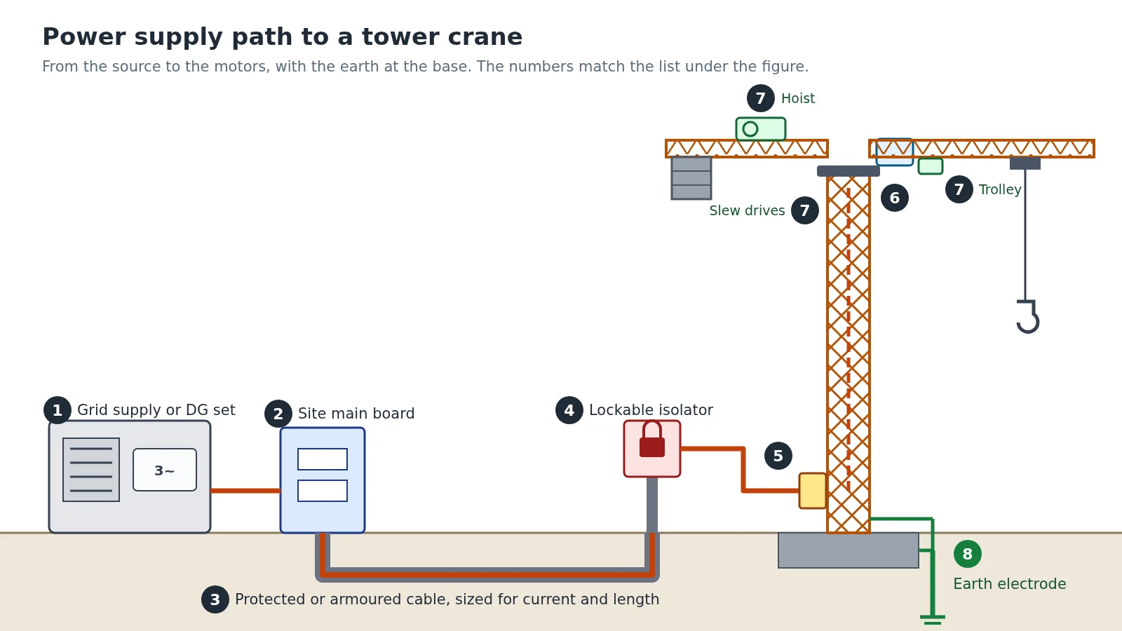
- Grid supply from the electricity board, or the site’s DG set.
- Site main board, with an outgoing breaker for the crane feeder.
- Cable to the mast base, run in conduit, trunking or trays, clipped where it is protected, or armoured.
- An identified, lockable isolator away from the crane that cuts the supply to the whole crane (IS 13367-1, clause 11.4 g).
- The crane’s own isolating switch on its structure, reachable from ground level, with its cover interlocked so it opens only when the switch is off (IS 6521-1, clause 37.1).
- The collector ring at the slewing ring, which keeps the electrical connection, earth included, between the fixed mast and the turning part (IS 6521-1, clause 43.2).
- The hoist, trolley and slewing motors with their drives.
- The earth electrode at the base, bonded to the crane structure, motor frames and every metal enclosure.
The cable. IS 13367-1, the Indian code for the safe use of cranes, asks for supply cables to be protected from mechanical damage in one of three ways: run in conduit, trunking or on trays, clipped to a structure where they are protected, or of armoured construction. Where that protection is metal, it is bonded to earth at each end, and it is never used as the earth conductor (clause 11.4 d). IS 6521-1 adds that a flexible cable liable to be run over by traffic needs take-up gear, and that a trailing cable is supported where it ends so the connections carry no strain (clauses 40.2 and 40.3). A crane that travels on rails is fed through a cable drum or a protected collector system, and its travel must stay well inside the length of the trailing cable (IS 13367-1, clause 11.4 e and f).
The cable size. It follows from the current in the table, the length of the run and the voltage drop allowed. IS 6521-1 names ambient temperature, grouping of cables and voltage drop as the factors to weigh (clause 39.4.2). With IS 732’s 5 percent limit on a grid supply, a 415 V crane feeder may lose about 21 V, leaving at least 394 V at the crane. That sits comfortably inside the 360 to 440 V window. For runs longer than 100 m, IS 732 allows a further 0.005 percent per metre, capped at an extra 0.5 percent. The drop is largest when the hoist lifts at full speed, because that is when the crane draws its highest current. The electrician picks the conductor size from the cable maker’s rating tables for that current and length.
The earth. The crane structure, motor frames and the metal cases of all electrical equipment, including conduit and cable guards, are connected directly to earth (IS 13367-1, clause 11.4 a and b; IS 6521-1, clause 43.1). On a rail-mounted crane at least one rail is bonded at every joint and earthed, and the crane’s wheels are never used as its earth path. IS 3043 adds that building sites are damp and rough, so the earthing has to be robust and regularly inspected (clause 34.1). The base and its other site checks are covered in the guide to the tower crane foundation.
The small loads. IS 6521-1 also asks for warning lamps for air traffic and an anemometer (wind meter) with an electrical interlock (clauses 42.3.1 and 42.3.1.1), so their circuits are part of the crane’s electrics. How the anemometer stops the crane is explained in the guide to the tower crane wind speed limit, and when a tall crane near an airport needs clearance in the post on the AAI NOC for height clearance. A handlamp circuit on the crane must not exceed 25 V AC (clause 42.1).
How much electricity does a tower crane use per hour?
Far less than its required power suggests, because the motors work in short bursts. The hoist pulls hard while it lifts and much less while it lowers or waits for the next load to be slung. The trolley and slewing motors are small and run for seconds at a time.
There is a hard ceiling. A crane cannot use more energy in an hour than its installed motor power running flat out for that hour: about 34 kWh for the MDT 109, 52 kWh for the MDT 249 J10 with its 50 hp hoist, and 112 kWh for the MD 689 M25 with its 110 hp hoist. No real shift comes close.
To estimate a real figure, multiply each motor’s power by the time it actually runs. Here is the arithmetic for an MDT 249 J10, using a made-up shift pattern only to show the method: if in one hour the 37 kW hoist works at full power for 15 minutes and the trolley and slewing motors (15 kW together) for 20 minutes, the crane uses 37 x 15/60 plus 15 x 20/60, about 14 kWh. Your own pattern will differ.
The reliable figure comes from an energy meter on the crane’s feeder, read at the start and end of each day. A week of readings gives the units per shift for that crane on that job, and the board’s bill or the DG set’s fuel log does the rest. Tariffs and diesel prices change too often to quote here.
Every crane in the table runs entirely on electric motors. Battery and cable-powered excavators and other machines are covered in the electric construction machines guide.
What should you check before the crane is connected?
IS 6521-1 sets out what each side must tell the other. The buyer states the nature of the electricity supply: AC voltage, frequency, number of phases and wires, any local bye-laws, the type and position of plug boxes or supply points, and whether a cable drum is needed (Appendix A). The maker states the power supply the crane needs, the number, type and rating of its motors, their full-load power and speed, the maximum current demand from the mains and the control gear (Appendix B). Before the crane goes live, run through this list:
- You have the crane’s data sheet with both required-power figures, the voltage window and the maximum current.
- The supply, grid or DG set, delivers the full required power with the crane’s other loads on it.
- The cable is sized for the current, the run length and the voltage drop, and protected or armoured along its route.
- A lockable isolator away from the crane cuts power to the whole crane, and the crane’s own isolating switch works from ground level.
- The earth electrode is in, and the structure, motor frames and enclosures are bonded to it.
- The supply and the crane equipment have been checked as compatible before connection (IS 13367-1, clause 11.4 c).
- The insulation resistance of every circuit reads at least 2 megohms, as IS 6521-1 requires at testing (clause 44.1).
The checks that follow on the first day of work, from limit switches to the emergency stop, are in the tower crane inspection checklist. Machines for the rest of a building job are set out on the building construction equipment page, and more crane guides are on the crane guide hub.
Planning lifts for a building project? Compare mobile crane models for erection and early lifts, and connect with a dealer near your site.
Where the figures in this guide come from. Motor powers, required power, voltage tolerance, speed ranges and the Power Control note are from Potain’s EN 14439 data sheets for the Evy 30-23, MDT 109, MDT 249 J10 and MD 689 M25, and the power limiter wording from Potain’s MDT CCS range brochure, all read in November 2026; Potain models are used here as fully published examples. The single-phase, controller, isolator, cable, main supply, lighting, earthing and testing clauses are from IS 6521 (Part 1):1972, clauses 35 to 44 and Appendices A and B. The electrical supply rules at the crane are IS 13367 (Part 1):1992 clause 11.4. Building site supply and earthing are from IS 3043:2018, clause 34, and the voltage drop limits from IS 732:2019, Annex Y, Table 47. Installed motor power, current, voltage drop and the energy example are our own arithmetic.
Prices, specifications and features are indicative, vary by variant, location and date, and should always be confirmed with the official OEM or authorised dealer before any purchase decision. DesiMachines is not liable for decisions taken on the basis of information that may have changed after publication.