
 Excavator
316 models
 Backhoe Loader
54 models
 Crane
68 models
 Concrete Mixer
79 models
 Wheel Loader
65 models
 Compactor / Roller
45 models
 Motor Grader
42 models

 Concrete Pump
66 models
 Skid Steer Loader
11 models


On its own plot, a batching plant takes up less ground than anything around it. Putzmeister gives a 30 m³/hour MT 0.5 plant a space of 14 m by 5 m, yet a working yard around it, with stockpiles, a loader turning area and a lane for transit mixers, comes to about 2,000 m² (roughly half an acre) in the worked plan below. A good batching plant layout brings material in at one end, sends concrete out at the other, and never makes a loaded truck reverse.
This guide takes the layout piece by piece: how much land each plant size needs, where the bins, silo, water and admixture tanks go, how much room the loader and the trucks need, and a sample plot for a 30 and a 60 m³/hour plant. The figures come from three places, all read on 22 November 2026: the Indian Standard for batching and mixing plants, IS 4925:2004; the “space required” figures Putzmeister prints for its MT plants on its South-East Asia site, which carries the Indian brochures; and the dimensions of the loaders and transit mixers sold in India. Where a number is our own arithmetic, the text says so.
How much land does a batching plant need?
Two different areas get called “space required”, and mixing them up is how plots end up too small. The first is the plant’s own footprint: the bins, conveyor, mixer and control cabin standing on the ground. The second is the working yard: the plant plus stockpiles, the loader’s turning space, the cement silo, tanks, the truck lane and a washout. Makers publish only the first.
Putzmeister’s model pages list the plant footprint as length by width, with the plant height and the height at which concrete drops into a truck:
| Plant and version | Output | Space required (L × W) | Plant height without silo | Discharge height | Aggregate bins |
|---|---|---|---|---|---|
| MT 0.35, inclined belt and compartment bins | 21 m³/hour | 10 × 4 m (40 m²) | 4.5 m | 1.75 m | 4 compartments, 12 m³ in all |
| MT 0.5, inclined belt and compartment bins | 30 m³/hour | 14 × 5 m (70 m²) | 8.4 m | 4.1 m | 4 × 6 m³ = 24 m³ |
| MT 1.0, compact belt and compartment bins | 54 m³/hour | 16 × 5 m (80 m²) | 10 m | 4.1 m | 4 × 10 m³ = 40 m³ |
| MT 1.0, inclined belt and inline bins | 60 m³/hour | 37 × 5 m (185 m²) | 10.75 m | 4.1 m | 4 × 12.5 m³ = 50 m³ |
| MT 2.0, inclined belt and inline bins | 90 m³/hour | 45 × 8 m (360 m²) | 13 m | 4.2 m | 4 × 25 m³ = 100 m³ |
The MT 1.0 also comes with a skip hoist in place of the belt, needing 17.5 × 5 m with compartment bins and 24 × 5 m with inline bins. So the same 60 m³/hour mixer can need anything from 16 m to 37 m of length, depending only on how the aggregate is stored and lifted. Pick the bin and conveyor arrangement before you buy or lease land, because it sets the shape of the plot.
The working yard is several times bigger than any of these. In the sample plans further down, a 30 m³/hour plant needs about 50 × 40 m (2,000 m²) and a 60 m³/hour plant about 75 × 46 m (3,450 m², a little under an acre). Those are our worked examples for a plant that runs on loose stockpiles with a wheel loader, and they shrink if aggregate arrives in tippers straight into ground hoppers. How the plant itself works, bin to mixer to truck, is covered in types of batching plant and how they work.
What goes where in a batching plant layout?
Lay the plot out along the path the material takes. Sand and aggregate arrive by tipper and sit in stockpiles. A loader carries them to the bins. A belt or skip lifts them to the mixer. Cement comes by screw conveyor from the silo, water and admixture from their tanks, and the mixed concrete drops into a transit mixer standing under the chute. Every item on the plot should sit on that line, close to the point where it joins it.
| Part | Where it goes | Why |
|---|---|---|
| Sand and aggregate stockpiles | At the bin end, in separate bays for each size | IS 4925 asks for separate storage for each size of fine and coarse aggregate (clause 5.1); short loader trips |
| Loader working area | Between stockpiles and bins, kept clear | The loader turns here 15 or more times an hour on a 30 m³/hour plant |
| Aggregate bins and conveyor | In line with the mixer | Fixed by the plant design; the bins face the loader |
| Cement silo | Beside the mixer, within the screw conveyor’s reach | The screw carries cement to the weigh hopper; a bulker tanker must also reach the silo to fill it |
| Water and admixture tanks | Close to the mixer platform | IS 4925 wants the admixture tank at the batcher floor for gravity feed (clause 6.5.1) |
| Control cabin | With a clear view of the discharge point | The operator watches each truck load; clause 5.2 asks for a cabin sealed against dust and rain water |
| Truck lane | A one-way loop under the mixer chute | Trucks queue, load and leave without reversing past the plant |
| Compressor, DG set and panels | Near the plant, away from the dust of the stockpiles | Short cable and air runs; dust kills filters and radiators |
| Washout and settling pit | At the low corner, on the truck exit side | Trucks wash on the way out and the slurry runs downhill |
| Site office and test lab | At the gate | Visitors and delivery-note checks stay out of the truck loop |
How big should the aggregate storage be?
The bins on a compact plant are smaller than most buyers expect. In the material calculation for M20 concrete in a 1 : 1.5 : 3 mix, one cubic metre of concrete uses about 0.42 m³ of sand and 0.84 m³ of aggregate, so 1.26 m³ of loose material goes in for every cubic metre that comes out. At a full 30 m³/hour that is about 38 m³ of sand and aggregate an hour. The MT 0.5’s four bins hold 24 m³, which lasts about 38 minutes at full output (our arithmetic). The 60 m³/hour MT 1.0 with 50 m³ of bins lasts about 40 minutes. Real design mixes for ready-mix concrete vary, but the lesson holds: the bins are a buffer, and the stockpiles and the loader keep the plant running.
IS 4925 gives two numbers to plan around. Clause 5.1.1 asks the buyer of a boom scraper plant (one where a scraper arm drags aggregate from open storage into the batcher) to keep enough aggregate for one hour of continuous running. And Annex A-1 tells the buyer to work out plant capacity at 75 percent efficiency, which means a 30 m³/hour plant should be counted on for about 22.5 m³ an hour across a shift.
On that basis, an eight-hour shift at 22.5 m³/hour is 180 m³ of concrete. In the same M20 proportions that needs about 76 m³ of sand and 151 m³ of aggregate split between the sizes, every working day (our arithmetic). Keep at least one day’s stock on the ground so a late tipper does not stop the plant. Each size needs its own bay, and the standard’s list of storage types for a buyer to choose from (clause 4.1) starts with “open storage with retaining walls”, which keeps sizes apart and lets a loader push into the pile without spreading it. Leave a firm, drained floor under the bays: sand standing in water carries extra moisture into the mix.
The cement side is sized separately. IS 4925 Annex A-7 lists silo sizes of 20, 30, 45, 60 and 75 tonnes, and the cement silo capacity guide works out how many tonnes a plant burns in a day and how big a silo that takes.
How much room does the loader need?
Plan the loader area from the machine’s turning radius over the bucket, the widest circle it sweeps when it turns at full lock. Two wheel loaders sized for a 30 m³/hour plant show the numbers:
| Model | Bucket capacity | Length with bucket | Turning radius over bucket | Loads an hour to feed 30 m³/hour |
|---|---|---|---|---|
| SDLG L940Hi | 2.4 m³ | 7,360 mm | 6,100 mm | about 16 |
| XCMG XC938 | 2.2 m³ | 7,450 mm | 6,022 mm | about 17 |
A turning radius of about 6.1 m means the loader sweeps a circle about 12.2 m across. Keep a clear strip of about 13 m between the face of the stockpiles and the front of the bins, so the operator can fill the bucket, turn and tip into a bin without a three-point shuffle. The last column is 37.8 m³ an hour divided by the bucket size, so a loader on a busy plant tips a bucket every three to four minutes all shift. A backhoe loader can stand in on a slow day, but the JCB 3DX‘s front shovel holds 1.0 m³, so it would need about 38 trips an hour to keep a 30 m³/hour plant at full output (our arithmetic), and the plant ends up waiting on the loader. The full range of wheel loaders lists the bucket and turning figures for each model.
Two smaller rules save trouble. Keep the loader’s path off the truck lane altogether, because a loader backing out of a bin and a transit mixer creeping forward are the classic plant-yard collision. And give the bins a ramp or a loading wall at the right height: the bucket has to clear the bin edge when tipping.
How should transit mixers move through the plant?
Plan a one-way loop: trucks come in, queue, drive under the chute, load, wash and leave by a different side. Putzmeister lists “easy drive-through, transit mixers don’t have to drive in reverse” as a feature of the MT 0.5, and on a busy plant this is the single most useful layout decision. A loaded truck reversing past the control cabin, the silo legs and a loader is where yard accidents happen.
The queue length comes from the trucks. Three transit mixers sold in India show the spread:
- The Eicher Pro 6028TM is 7,677 mm long and 2,496 mm wide.
- The Tata Signa 2830.K 8 Cum REPTO RMC is 8,084 mm long and 3,010 mm wide.
- The BharatBenz 2828C RMC is 9,475 mm long.
One truck under the chute and two waiting, with about 3 m between them, needs roughly 35 m of straight lane (our arithmetic on the longest truck). The lane itself should be at least 4 m wide for a truck about 2.5 to 3 m wide, with room to walk past.
How often the trucks come decides how long the queue gets. The MT 0.5 mixes 0.5 m³ a batch, so a 6 m³ drum takes 12 batches; at the full 30 m³/hour a 6 m³ truck fills every 12 minutes. A late truck holds up the plant, and two early ones block the gate. Truck types and drum sizes are listed in the range of transit mixers.
Check one height before the plant is ordered. IS 4925 Annex A-16 asks the buyer to state the discharge height needed, “depending upon transportation of mixed concrete by dumper or transit mixer”. Putzmeister’s MT 0.5 and MT 1.0 discharge at 4.1 m, sized for a transit mixer’s hopper, while the small MT 0.35 discharges at 1.75 m, which suits a dumper or a pan. Measure the hopper height of the trucks you will actually use.
Where do the cement silo, water and admixture tanks go?
The cement silo stands beside the mixer, as close as its screw conveyor allows. MEKA’s spec sheet for its S30 job-site plant lists a cement screw conveyor 193 mm across and 5,000 mm long, which gives a sense of the distance involved: the silo foot is a few metres from the cement weigh hopper, not across the yard. A longer screw is possible, but it is slower and wears faster. Leave a road on the far side of the silo so a bulk cement tanker can park beside it and blow cement in through the filling pipe without crossing the truck loop.
IS 4925 clause 5.1 draws a line at 30 m³/hour. Below it, a cement hopper with a screw conveyor or a manual arrangement is enough. From 30 m³/hour up, the cement weigh batcher must stand on its own independent structure, with a watertight cement compartment, an air vent and an emergency cut-off gate. A silo at that size is a matter of agreement between buyer and supplier.
Water comes next. Clause 6.4 calls for a reservoir tank with the plant, sized as agreed between buyer and supplier, piped so that water reaches the mixer without touching the cement or aggregate first. Size it from the water per cubic metre in your mix times a day’s output, plus truck washing; the water cement ratio guide gives the litres per bag for M20 to M30. Place the tank where a water tanker or a borewell line can reach it.
For admixtures, clause 6.5.1 wants a storage tank for each admixture solution at the batcher floor, fed by gravity, with a pump bringing it up from ground storage and a float switch holding the level. So the drums stand on the ground beside the plant, and the day tank sits up on the platform.
Sample plot plan for a 30 and a 60 m³/hour plant
These two plans add up the pieces above. They are worked examples, not maker drawings, and the maker’s own layout and foundation plan always comes first.
| Zone | 30 m³/hour compact plant | 60 m³/hour inline-bin plant |
|---|---|---|
| Plant footprint | 14 × 5 m (Putzmeister MT 0.5) | 37 × 5 m (Putzmeister MT 1.0, belt and inline bins) |
| Stockpile bays (one day’s stock) | About 12 m deep, three bays | About 15 m deep, running along the bins |
| Loader clear area | About 13 m | About 13 m, the full length of the bins |
| Truck lane and queue | About 35 m of one-way lane | About 35 m in, plus exit past the washout |
| Silo, tanks, cabin, compressor, DG set | Beside the mixer end, about 6 to 8 m strip | Beside the mixer end, about 8 m strip |
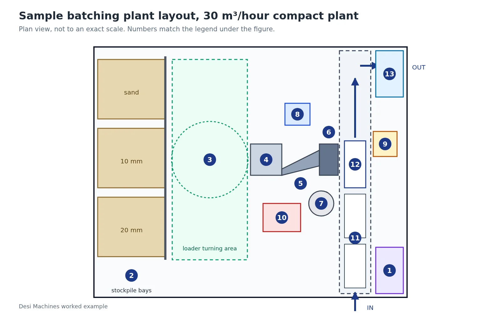
| Overall plot | About 50 × 40 m = 2,000 m² (about 0.5 acre) | About 75 × 46 m = 3,450 m² (about 0.85 acre) |
On the 30 m³/hour plot (Figure 1), the stockpiles take the back 12 m, the loader works in the next 13 m, and the plant stands in the middle with its mixer end towards the truck lane. The lane runs across the plot from the gate, under the chute and out past the washout. On the 60 m³/hour plot the bins are in a long line, so the stockpiles and the loader strip run along the plant’s 37 m length, and the truck lane crosses at the mixer end.
If the land is tight, two changes save the most space. Choose compartment bins over inline bins (the MT 1.0 drops from 37 m to 16 or 17.5 m), and have tippers drop aggregate into ground hoppers, which shrinks the stockpile yard. What you should not squeeze is the truck lane or the loader circle.
Foundations, drainage and power on the plot
Foundations depend on the plant type. A mobile or semi-mobile plant stands on firm, compacted ground or a concrete pad, while a stationary plant goes on foundations designed by its maker. IS 4925 clause 11.4 makes the maker supply the foundation plan and erection drawings, and clause 11.7 makes the maker guide the buyer when the buyer does the civil work. The ground-pressure figures and what each plant type needs underneath are set out under foundations in mobile vs stationary batching plant.
Drainage is the part most plots forget. Slope the whole yard gently towards one corner on the exit side and put the truck washout and a settling pit there, so slurry and rain water run away from the stockpiles and the plant. Trucks wash out their drums at the end of each day, and that grey water must settle before anything leaves the site. Your state pollution control board’s consent sets the conditions for discharge and dust, so ask for them before the plot is finalised.
Power and air sit close to the plant. The DG set or transformer, the main panel and the air compressor go in a protected corner near the mixer, out of the stockpile dust and away from the truck lane. The batching plant power consumption guide works out the DG set size, and the plant’s small compressor needs an air tank that suits it, as shown in the air receiver tank size calculation. Leave walkways and a crane or hydra access path to the mixer for liner and blade changes, which the batching plant maintenance guide lists by interval.
Choosing, setting up and running a plant are covered across the batching plant guides, and the companies that build plants in India are listed in our batching plant manufacturers in India roundup. When the plot is ready, compare transit mixer models for the fleet that will run the loop.
Sources
- Bureau of Indian Standards, IS 4925:2004 Concrete Batching and Mixing Plant, Specification: clauses 4.1, 5.1, 5.1.1, 5.2, 6.4, 6.5.1, 11.4, 11.7 and Annex A-1, A-7 and A-16.
- Putzmeister, MT 0.35, MT 0.5, MT 1.0 and MT 2.0 batching plant pages (South-East Asia site), read 22 November 2026: output, space required, plant height, discharge height and bin sizes.
- MEKA, S30 job-site concrete batching plant specification sheet (31 October 2022): cement screw conveyor size.
- Wheel loader and transit mixer dimensions from the catalogue specs of each model linked above, November 2026.
Prices, specifications and features are indicative, vary by variant, location and date, and should always be confirmed with the official OEM or authorised dealer before any purchase decision. DesiMachines is not liable for decisions taken on the basis of information that may have changed after publication.