
 Excavator
316 models
 Backhoe Loader
54 models
 Crane
68 models
 Concrete Mixer
79 models
 Wheel Loader
65 models
 Compactor / Roller
45 models
 Motor Grader
42 models

 Concrete Pump
66 models
 Skid Steer Loader
11 models


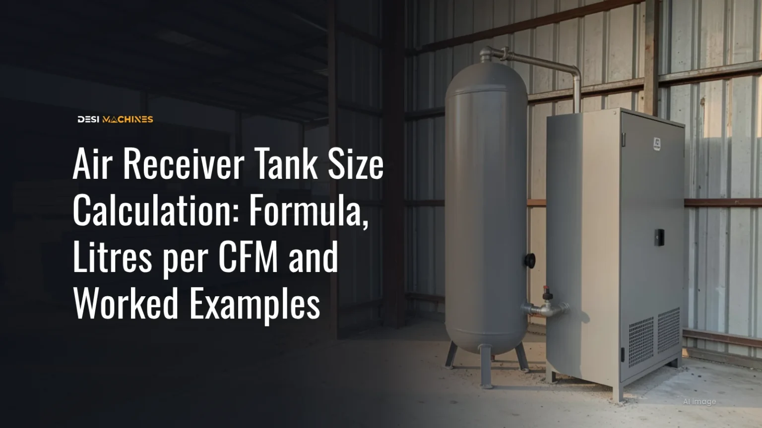
A screw compressor delivering 5 m³ of free air a minute (about 177 cfm) on load/unload control needs a receiver of roughly 650 to 1,300 litres, and the pressure band you set decides where in that range you land. The air receiver tank size calculation behind that answer takes four numbers from the compressor sheet and one from your controller, and this guide walks through it in litres and bar.
An air receiver is the steel tank between the compressor and the pipework. In a workshop, a precast yard, a crushing plant or a batching plant, it stores air, smooths out the swings in demand and gives water and oil a place to settle before the air reaches the line. Too small, and the compressor loads and unloads every few seconds while pressure at the tools jumps about. Too large costs money and floor space for no gain. The method below uses three sources, all read on 22 November 2026: the Indian Standard for air receivers, IS 7938:2023; Atlas Copco India’s page What is an air receiver? (22 October 2024); and the sizing formulas in the Atlas Copco Compressed Air Manual, 9th edition (2019).
What does an air receiver tank do?
An air receiver stores compressed air so the compressor does not have to match every change in demand second by second. IS 7938 gives it two jobs. Clause 4.1 says the receiver dampens the pulses from a piston machine and helps condense and trap moisture, letting oil and dirt settle before the air goes into the pipes. Clause 4.2 calls the second job a “flywheel effect”: the tank meets varying demand “without compressor regulation functioning incessantly”.
Atlas Copco’s page splits receivers into two kinds by where they sit. A wet receiver stands between the compressor and the dryer and holds air that has not yet been dried; it takes load off the dryer by catching water first. A dry receiver stands after the dryer and holds treated air close to where it is used. Most small sites have only the wet one.
Small piston compressors often come “tank-mounted”, sitting on top of their own receiver. Atlas Copco says this is common up to about 26 kW (35 HP); larger machines become top-heavy and stand beside a separate tank. Why a piston machine needs a tank at all, and a screw machine less so, is explained in screw vs piston air compressor.
What is the minimum receiver size as per IS 7938?
IS 7938:2023 clause 6.1 sets a floor: the receiver’s capacity should be one-tenth of the compressor’s free air delivery per minute, rising to about one-sixth for smaller compressors. Free air delivery (FAD) is the air the compressor actually delivers, measured as the volume it would take up at the intake. The standard calls this a minimum and adds that “a much bigger capacity” is needed if you want real storage.
Put into numbers, a compressor with an FAD of 5 m³/min needs at least 0.5 m³, or 500 litres, by the one-tenth rule, and up to 833 litres if you treat it as a small machine and use one-sixth. A 1 m³/min workshop machine needs at least 100 to 167 litres.
Two lines in the same clause are easy to miss. The rule “is not applicable to portable compressors”, which matters on road and quarry sites (see the section on portable machines below). And for rotary (screw) compressors, this receiver is “in addition to the receiver forming part of the compressor design”, so the separator vessel inside a screw package does not count towards it.
If you are unsure of your compressor’s FAD, or the sheet gives it in cfm at different conditions, the air compressor cfm calculation guide explains free air, scfm and brochure figures. For conversions: 1 m³/min is 16.67 litres per second (l/s), and 1 cfm is 0.472 l/s.
How do you calculate air receiver tank size from cfm and pressure?
For a compressor on load/unload control, the Atlas Copco Compressed Air Manual sizes the receiver so the compressor never cycles faster than it is built to. The formula is:
V = (0.25 × qc × p1 × T0) ÷ (fmax × (pU − pL) × T1)
Each letter is a number you can find on the compressor sheet or the controller:
- V is the receiver volume in litres.
- qc is the compressor FAD in l/s.
- p1 is the inlet pressure in bar absolute; at the plains, use 1.
- T1 is the highest intake air temperature in kelvin (°C + 273).
- T0 is the temperature of the air in the receiver, in kelvin. The manual’s example takes 10 °C above the intake for an aftercooled screw compressor.
- fmax is the most load cycles the compressor allows. For Atlas Copco machines the manual uses one cycle every 30 seconds, written 1/30.
- pU − pL is the gap between the unload and load pressures, in bar. A compressor that loads at 7.0 bar and unloads at 7.5 bar has a band of 0.5 bar.
The pressure band does most of the work in this formula. Halve the band and the tank doubles; double it and the tank halves. Temperature barely moves the result, because T0 and T1 appear as a ratio that stays close to 1. A 40 °C Indian summer intake gives almost the same volume as the manual’s 30 °C example.
Three more rules from the same manual matter on real installations. Where several compressors feed one receiver, size it on the largest compressor. For a variable speed drive (VSD) compressor, put in the FAD at minimum speed, which gives a much smaller tank. And the answer is a minimum: “The next larger standard size is usually selected.”
Atlas Copco’s India page also gives a quick rule of thumb: 10 to 15 litres of receiver for every l/s of compressor output, depending on the compressor type and the job. The same page states it as 3 to 4 gallons per cfm, but that converts to roughly 24 to 32 litres per l/s, so the two versions do not agree. With a metric compressor sheet, use the litre figure, then check it with the formula.
Worked example: sizing the receiver for a 5 m³/min screw compressor
Take an electric screw compressor in a precast yard or a crushing plant workshop. Its sheet gives an FAD of 5 m³/min at 7 bar, and it loads at 7.0 bar and unloads at 7.5 bar. The site is in the plains and the shed reaches 40 °C in May.
Step 1. Convert FAD to l/s: 5 × 16.67 = 83.3 l/s.
Step 2. Set the temperatures: T1 = 40 + 273 = 313 K. Following the manual’s example, the air in the receiver is 10 °C warmer, so T0 = 323 K.
Step 3. Put in fmax = 1/30, p1 = 1 bar and a band of 0.5 bar:
V = (0.25 × 83.3 × 1 × 323) ÷ (1/30 × 0.5 × 313) = 6,726 ÷ 5.22 = about 1,290 litres.
Step 4. Widen the band to 1.0 bar (load at 6.5, unload at 7.5) and the answer halves to about 645 litres. The catch is that the tools now see pressure falling to 6.5 bar between cycles, so the band must stay above what the tools need.
Step 5. Pick the next larger stock size above your answer, for example a 1,500-litre receiver for the 0.5 bar band.
Here is how the three methods compare for this one compressor:
| Method | Working | Receiver volume |
|---|---|---|
| IS 7938 cl 6.1 minimum, one-tenth of FAD per minute | 5 m³ ÷ 10 | 500 litres |
| IS 7938 cl 6.1, one-sixth for smaller compressors | 5 m³ ÷ 6 | about 833 litres |
| Atlas Copco rule of thumb, 10 to 15 litres per l/s | 83.3 × 10 to 83.3 × 15 | 833 to 1,250 litres |
| Load/unload formula, 1.0 bar band | fmax 1/30, T1 313 K, T0 323 K | about 645 litres |
| Load/unload formula, 0.5 bar band | same, band halved | about 1,290 litres |
The standard’s figure is the floor, the rule of thumb is a quick sanity check, and the formula is the one to trust because it uses your own pressure band. When they disagree, go with the larger of the formula and the IS 7938 minimum.
The same formula explains why a small piston compressor on start-stop control needs a bigger tank than its size suggests. IS 6206:2023, the standard for choosing compressor plant, says in clause 11.2 that start-stop control is generally not used once the machine would start more than six times an hour. Hold a 500 litre-per-minute (8.3 l/s) piston compressor with a 2 bar pressure-switch band to six starts an hour (fmax = 6/3,600), and the formula gives about 645 litres. At one cycle every 30 seconds it would need only 32 litres, which shows how much of the tank on a piston machine is there to protect the motor from frequent starts. Many small tank-mounted units are built for more starts than that; the motor maker’s limit is the one to use.
How big a receiver do you need for short bursts of heavy air use?
When a job takes a lot of air for a short time, such as blowing down moulds, a short sandblasting run or filling large tyres, the manual sizes the receiver to cover the burst on its own:
V = (q × t) ÷ (p1 − p2)
Here q is the extra air flow during the burst in l/s, t is how long the burst lasts in seconds, p1 is the normal line pressure and p2 is the lowest pressure the job can still work at, both in bar. The manual’s own example is 200 l/s for 40 seconds with the pressure allowed to fall by 0.92 bar, which needs about 8,700 litres.
Two smaller cases show where storage helps and where it does not:
| Burst | Working | Receiver volume |
|---|---|---|
| 60 l/s for 30 seconds | 60 × 30 ÷ 1.5 | 1,200 litres |
| 40 l/s for 3 minutes | 40 × 180 ÷ 1.5 | 4,800 litres |
The first is a sensible tank. The second is a big vessel for one tool, and it would be cheaper to give that job more compressor. A receiver covers short peaks; it does not replace compressor capacity for anything that runs for minutes at a time.
The formula also leaves out the refill. After a burst the compressor has to put the air back, so it needs spare capacity above the normal demand. For the 1,200-litre case, the receiver gives up 1,200 × 1.5 ÷ 1.013, or about 1,780 litres of free air. With 10 l/s to spare, the compressor refills it in about three minutes, which is fine for a burst every few minutes and not fine for one every 30 seconds. Atlas Copco’s manual also suggests placing such a receiver near the point of use, and IS 7938 clause 5.1.1 says the same for long lines: it pays to put one or more receivers farther along the system or at a point of intermittent heavy demand.
How long can an air receiver supply air?
IS 7938 clause 6.1.1 gives the formula for a receiver used as storage:
T = V × (P1 − P2) ÷ (C × P0)
T is the time in hours, V the receiver volume in m³, P1 the full pressure and P2 the lowest usable pressure (both in bar absolute), C the free air drawn per hour in m³, and P0 atmospheric pressure in bar. Absolute pressure is the gauge reading plus about 1 bar; since the formula uses the difference P1 − P2, the gauge readings give the same gap.
A worked case: a 1,000-litre (1 m³) receiver charged to 8 bar on the gauge, feeding a blow gun and an impact wrench that together draw, say, 0.6 m³ of free air a minute (36 m³ an hour), with the tools still working at 6 bar. The tank holds 1 × 2 ÷ 1.013, or about 1.97 m³ of usable free air. That lasts about 3.3 minutes with the compressor off. This is the honest number to know before a power cut or a compressor trip, and it is why a receiver alone cannot keep a crew working for long.
Does a portable site compressor need a separate receiver?
Usually not for breakers and rock drills. IS 7938 says its one-tenth rule does not apply to portable compressors. A towed diesel screw compressor carries its own separator tank, where oil drops out of the air before it reaches the hose, and it runs on load/unload or speed control to follow the tools. A breaker crew draws a steady flow while it works, which is a job for compressor capacity, not storage. How many breakers one compressor can feed is worked out in the compressor breaker machine guide.
A separate receiver starts to make sense when a portable machine stands in one place for months and feeds a fixed line: a site workshop, the pneumatic gates on a batching plant, or a precast yard’s cleaning and vibrator points. Then it behaves like a stationary installation and the formulas above apply. Batching plants are a common case: the batching plant power consumption guide shows the small piston compressor on a 30 m³/hour plant switching on and off to keep its air tank at pressure. For shotcrete, size for the nozzle’s continuous flow first; the shotcrete guide covers the method.
The types of compressor used on sites, and when a portable or a stationary machine suits the job, are compared in air compressor for construction.
What safety fittings and tests must an air receiver have?
A receiver is a pressure vessel, and IS 7938:2023 sets out what it must carry. It applies to fusion-welded receivers with a design pressure up to 25 bar (clauses 1 and 3.1), made to IS 2825, with the design pressure taken as the maximum working pressure plus 10 percent (clause 8).
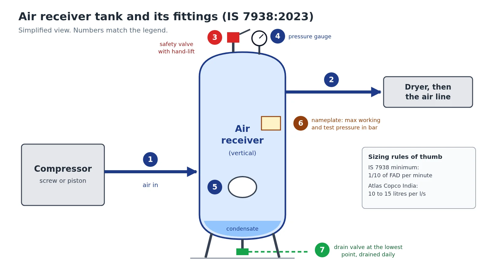
| Item | What the standard asks | Clause |
|---|---|---|
| Safety valve | At least one, preferably direct spring-loaded, letting air out so the pressure never rises more than 10 percent above working pressure with the compressors at full output and every outlet shut | 9.1 |
| Hand-lift and cap | Hand lifting gear that can lift the spindle at not less than 75 percent of working pressure; a cap or ferrule so the setting cannot be screwed up by mistake | 9.1.1, 9.1.2 |
| Drain valve | A manual or automatic drain at the point where condensate collects | 9.2 |
| Pressure gauge | Bourdon type to IS 3624, dial in bar, reading from zero to between 1.5 and 2 times the design pressure | 9.3.1 |
| Fusible plug (optional) | May be fitted against fire; placed so its discharge cannot hurt anyone | 9.4 |
| Inspection openings | Two openings of 30 mm bore on a vessel up to 230 mm inside diameter, rising to a manhole (at least 450 mm) or two 150 × 100 mm elliptical holes from 900 mm | 10 |
| Hydraulic test | At the maker’s works, 1.5 times design pressure held for 30 minutes, seams struck with a hammer while under pressure | 11.2 |
| Periodic inspection | Once every 5 years, as per PESO (Petroleum and Explosives Safety Organisation) guidelines | 11.1 |
| Nameplate | Maker, maximum working pressure, test pressure, standard, date of test and year of manufacture | 14.1 |
Where the tank stands matters too. Clause 5.1 prefers outdoors or an open shed for cooling, and a vertical tank on a skirt or legs so the condensate runs to the drain. Atlas Copco advises draining the receiver at least once a day, more often when the compressor runs fully loaded, and suggests a float, timer or electronic drain so it is never forgotten. It also says the receiver’s rating should sit above the compressor’s: a fixed-speed compressor rated for 8 bar should feed a receiver rated for at least 10 bar.
Before you buy a used receiver or move one to a new site, read the nameplate. If the maximum working pressure is below your compressor’s unload pressure, or the test date is missing, the tank is not fit for the job, however good it looks. The daily drain and the safety valve check belong with the rest of the compressor’s routine in the air compressor maintenance guide.
Need compressed air for a job without buying the plant? You can find machines on rent near your site, and the air compressor guides cover sizing, types and upkeep for the compressor itself.
Sources
- Bureau of Indian Standards, IS 7938:2023 Air Receivers for Compressed Air Installation, Specification (First Revision), March 2023: clauses 4 to 14, read from the archive.org scan with the formula and tables checked on the page images.
- Bureau of Indian Standards, IS 6206:2023, clause 11.2 on start-stop control.
- Atlas Copco India, What is an Air Receiver?, 22 October 2024: wet and dry receivers, tank-mounted compressors, the 10 to 15 litres per l/s rule, daily draining and receiver pressure rating.
- Atlas Copco, Compressed Air Manual, 9th edition (2019), section 3.6.1.1 and chapter 5: the load/unload receiver formula, the intermittent-demand formula and their worked examples.
Prices, specifications and features are indicative, vary by variant, location and date, and should always be confirmed with the official OEM or authorised dealer before any purchase decision. DesiMachines is not liable for decisions taken on the basis of information that may have changed after publication.