
 Excavator
316 models
 Backhoe Loader
54 models
 Crane
68 models
 Concrete Mixer
79 models
 Wheel Loader
65 models
 Compactor / Roller
45 models
 Motor Grader
42 models

 Concrete Pump
66 models
 Skid Steer Loader
11 models


A nonel blast sends its firing signal down a plastic tube about 3 mm thick instead of an electric wire, at roughly 2,000 metres a second. Each tube ends in a delay detonator inside the blast hole, so every hole fires at its own planned millisecond, one after another, and never all at once.
Nonel is short for “non-electric”. It began as a trade name of the Swedish company Nitro Nobel, which developed the shock tube in the 1960s and 1970s (the business is now part of Dyno Nobel). Quarry and mine crews in India use the word for any shock tube system, whoever makes it.
This guide explains how the tube carries the signal, what goes into a nonel hook-up, how it compares with electric and electronic detonators and with detonating cord, and how delay timing between holes and rows cuts ground vibration and flyrock. The holes themselves are covered in the guide to blast hole drilling, and the amount of explosive in them in the guide to powder factor in blasting.
What is nonel blasting?
Nonel blasting is rock blasting in which every hole is fired through a shock tube and a delay detonator, with no electric wire anywhere in the circuit. It is the usual way a stone quarry or opencast mine fires a multi-hole bench blast today.
Three things make up the system. A thin plastic tube carries the signal. A detonator (a small metal capsule holding a sensitive charge, also called a blasting cap) sits at the bottom end of that tube, pushed into a primer cartridge inside the hole. Surface connectors with their own built-in delays link one hole to the next on top of the bench.
The words used on site:
- An in-hole (or downhole) delay is the detonator inside the hole. Its delay is counted in milliseconds (thousandths of a second) from the moment the signal reaches it.
- A surface connector, also called a trunkline delay, is a short tube with a small delay unit in a plastic block. It clips onto the tube of the next hole and passes the signal on after a set delay.
- A lead-in line is a long reel of tube that runs from the bench to the place where the blaster stands to fire.
- A starter, or blasting machine, sets off the lead-in line.
How does a nonel shock tube work?
The inside wall of the tube carries a very thin coating of reactive powder. When the starter fires into the open end, that coating reacts along the whole length of the tube like a tiny dust explosion running down a pipe. The tube is not damaged by it, and on the surface it makes almost no noise.
The US Federal Highway Administration’s rock blasting manual (FHWA-HI-92-001, 1991) puts the coating at about 0.1 grain per foot of tube and the signal speed at about 6,000 feet a second. Dyno Nobel’s 2010 data for its lead-in line gives 2,100 m/s, plus or minus 300 m/s. At that speed the signal covers 100 metres of tube in roughly 50 milliseconds, a delay worth remembering on a long lead-in.
The US Bureau of Mines blasting manual (Information Circular 8925, 1983) and the FHWA manual list what makes the tube useful:
- It carries no current, so stray current, static and radio signals cannot fire it. A direct lightning strike still can, and IS 4081:2013 clause 7.1 says explosives are not handled during a thunderstorm or when one is expected.
- The reaction inside is too weak to set off the explosive the tube passes through. Only the detonator at its end fires the charge.
- It keeps firing through tight bends and kinks.
- It is nearly silent, unlike detonating cord laid on the surface.
The tube itself is started in one of several ways: a hand-held starter gun that fires a shotgun-type primer into it, a small battery blasting machine that puts a spark inside it (Dyno Nobel’s DynoStart runs on a 9-volt battery and needs both hands to fire), an electric detonator taped to it, or a length of detonating cord.
What delay numbers do nonel detonators come in?
Every in-hole detonator in a series carries a delay number, and each number has a fixed firing time. The number is printed on a colour-coded tag or clip at the top of the tube, so the crew can check every hole by eye before firing.
Makers sell two broad families. A millisecond (MS) series steps up in short intervals and suits surface benches. A long-period series steps in hundreds of milliseconds and suits tunnels, shafts and underground faces, where the rock needs time to move out of the way before the next hole fires.
Table 1: Example nonel delay series from one maker’s data sheet
| Product family | Where it is used | Delay range | Step between numbers |
|---|---|---|---|
| MS series in-hole detonators | Surface benches and underground | 25 ms (No. 1) to 1,000 ms (No. 28) | 25 ms up to 500 ms, then 50 ms and 100 ms |
| LP (long period) in-hole detonators | Tunnels, shafts, underground development | 25 ms (No. 0) to 8,000 ms (No. 18) | Mostly 300 ms to 800 ms |
| Surface connectors | Linking holes on top of a bench | 9, 17, 25, 42, 67, 109, 150, 176 and 200 ms | Each connector has one fixed delay |
| Lead-in line | From the bench to the firing point | No delay (reels of 100 to 1,000 m) | Not applicable |
Source: Dyno Nobel Blasting and Explosives Quick Reference Guide, 2010 (Australian product range), pages 19 to 22. Every maker uses its own numbers and colours, and ranges change, so read the current data sheet of the product on your site.
The tube on that maker’s standard in-hole units is 3.0 mm across, and the detonators are rated No. 12 strength. The Bureau of Mines manual notes that the nonel cap is stronger than most electric caps.
Nonel vs electric vs electronic detonators: what is the difference?
Four ways of firing a blast are in use. They differ in how the signal travels, how exact the timing is and whether the circuit can be tested before firing.
An electric detonator has two leg wires joined inside by a thin bridge wire. Current from an exploder heats the wire, which lights a delay element (a slow-burning powder column) and then the main charge. Detonating cord is a plastic-covered cord with a core of PETN explosive that itself detonates, very fast. An electronic detonator replaces the burning powder with a microchip that counts the delay.
Table 2: The four initiation systems compared
| System | How the signal travels | How the delay is made | Can the circuit be tested? | Main weak point |
|---|---|---|---|---|
| Electric detonator | Current through copper or iron leg wires | Burning powder delay element | Yes, with a circuit tester | Stray current, static, radio and lightning can fire it |
| Detonating cord | The cord itself detonates; IS 7526 asks for at least 6,000 m/s | Delay relays or connectors tied into the cord | By eye only | Loud on the surface; a cord downline can set off cap-sensitive explosive along the hole |
| Nonel (shock tube) | Low-energy reaction inside a plastic tube, about 2,000 m/s | Burning powder delay element in the detonator and connectors | By eye only; there is no wire for a tester to read | One cut or badly clipped tube leaves the holes after it unfired |
| Electronic detonator | Coded electrical signal from a logger and firing unit | Microchip, factory-set or programmed on site | Yes, each detonator answers the logger | Needs trained users, loggers and a secure firing unit |
The Indian standard for detonating fuse, IS 7526:1996, sets two common core loads, 6 g/m (cord 3.5 to 4.5 mm thick) and 10 g/m (4.25 to 5.5 mm), and a detonation speed of not less than 6,000 m/s.
Accuracy is where the systems split most. A powder delay element never burns in exactly the same time twice. The FHWA manual calls this cap scatter and puts it at about 1 to 15 percent of the rated delay on new caps, adding that age can shift it further. India’s standard for electric delay detonators, IS 7632:1975, accepts a batch if no more than 5 percent of tested detonators overlap the firing time of the next delay number. The electronic detonator standard, IS 18462:2023, asks for far tighter timing: within 2 ms of the set delay up to 1,000 ms, and within 0.2 percent beyond that.
IS 18462 also describes how electronic systems are controlled. Each detonator talks both ways with a hand-held logger, delays are either fixed at the factory or programmed on site, and the logger and firing unit are kept behind security access, with geo-fencing as an option. Below ground in a coal mine that needs safety lamps, the Coal Mines Regulations, 2017 allow only detonators and firing units approved by the Directorate General of Mines Safety (DGMS).
Why do delays cut ground vibration and flyrock?
Holes that fire together shake the ground as one big charge. Spread the same holes out in time and each one shakes the ground on its own, with a smaller kick. That is why vibration limits are worked out from the largest charge fired in any one delay, not from the total in the whole blast. The limits themselves, and how a seismograph measures them, are in the guide to blasting vibration limits as per DGMS.
Indian mining law writes delays into the rules. Under regulation 164(1-B) of the Metalliferous Mines Regulations, 1961, an opencast blast with a permanent building of another owner inside the danger zone may fire no more than 2 kg in all the holes fired at one time, unless the inspector allows more. If delay detonators separate successive shots by at least half a second, up to 2 kg may go in each hole. Closer than 50 m to such a building, no blast is fired without written permission.
Timing also decides where the rock goes. The FHWA manual explains that if the second row fires before the first row has moved, the second row faces a much bigger burden (the rock between a hole and the open face), cannot push forward, and blows out upwards. That is how a sound design throws flyrock and loud air blast. Its guideline for production benches is at least 2 and normally not more than 6 milliseconds between rows for every foot of burden, about 7 to 20 ms per metre. Between holes in the same row the manual’s constants run from about 0.9 ms per foot of spacing in the hardest rock to about 2.1 ms in soft rock.
A worked check: a limestone bench drilled at 3 m burden and 3.5 m spacing. Three metres is 9.8 feet, so the row-to-row window is roughly 20 to 59 ms, and a 42 ms surface connector falls inside it. Spacing of 3.5 m is 11.5 feet, so a 17 ms connector between holes works out to 1.5 ms per foot, inside the 1.2 to 1.8 range the manual gives for limestones. These are starting values for a trial blast, not a design; the blaster in charge adjusts them by watching how the rock breaks.
How is a nonel blast connected on the surface?
The safe habit is to give every hole the same long in-hole delay and let the surface connectors set the order. The Bureau of Mines manual explains why: if the in-hole delay is longer than the time the signal needs to cross the whole surface network, every detonator below ground is already lit before the first hole goes off. A flying rock or a moving burden can then cut a surface tube without causing a misfire. Its example uses a 75 ms delay in every hole and 9 ms trunkline delays.
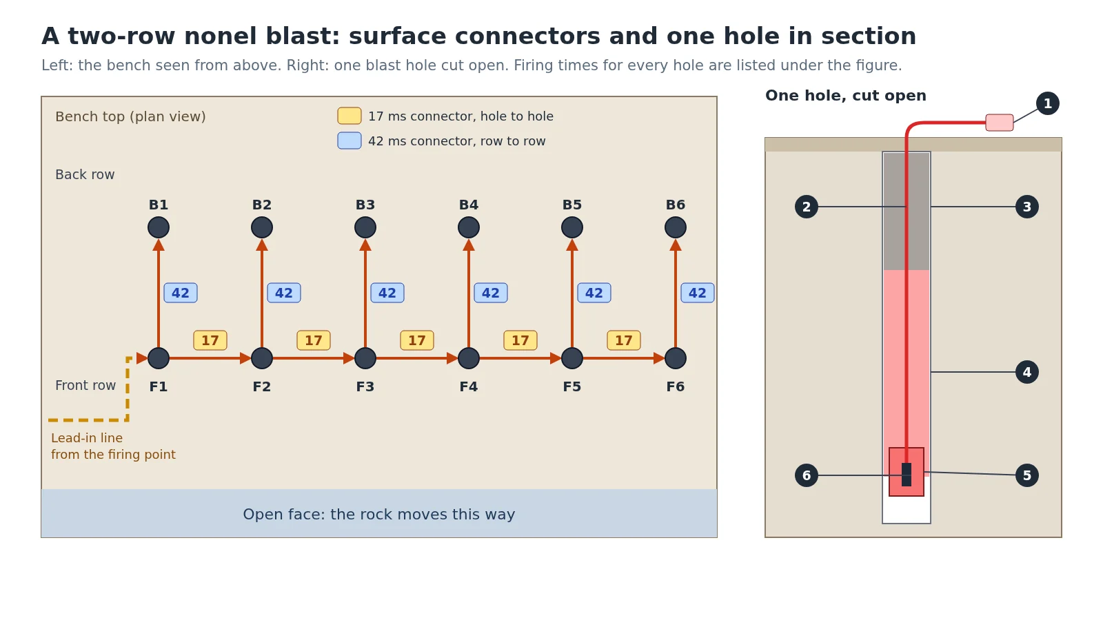
The numbers on the cut-open hole:
- Top end of the shock tube, clipped into a surface connector on the bench.
- Shock tube running down the hole to the detonator.
- Stemming: crushed stone packed into the top of the hole to hold the gas in.
- Explosive column.
- Primer cartridge, a small high-strength charge that the detonator sets off first.
- In-hole delay detonator, here a 500 ms unit.
In Figure 1 every hole holds a 500 ms in-hole detonator. The front row is tied hole to hole with 17 ms connectors, and each back-row hole is tied to the hole in front of it with a 42 ms connector. The signal reaches the last hole at 127 ms, long before the first hole fires at 500 ms. The firing times then work out as follows:
- Front row, holes F1 to F6: 500, 517, 534, 551, 568 and 585 ms.
- Back row, holes B1 to B6: 542, 559, 576, 593, 610 and 627 ms.
No two holes fire at the same moment, and the whole blast is over in about an eighth of a second after the first hole goes.
The layout also shapes the muckpile (the heap of broken rock). The FHWA manual notes that rock moves in the direction of the burden, that firing row by row spreads the rock out more, and that a V-shaped firing order, starting in the middle of the front row and opening out to both sides, piles it high and close to the face.
What goes wrong with nonel, and how is it checked?
Most nonel failures come from the tube, not the detonator. A tube that is cut, crushed under a stone, pulled out of its connector or clipped the wrong way round stops the signal there, and every hole fed through it stays unfired. Water inside an open tube end can do the same.
Because the circuit cannot be tested with a meter, the check is a walk along every line before firing: each tube seated in its connector, the delay tags matching the plan, no tube under a loose rock, and the lead-in line laid out of the way of vehicles.
A misfire is a charge that fails to detonate, and a cut-off is a hole sheared by an earlier hole in the same blast (both terms are defined in IS 10081). Regulation 167 of the 1961 regulations sets out what follows. Unless the blaster is certain every shot went off, nobody re-enters the blast area for 30 minutes; the five-minute exception in that rule is written for shots fired electrically, so it does not cover nonel. In an opencast working the misfired hole is marked with a red flag. If it cannot be re-primed and fired, a relieving hole is drilled no closer than 30 cm to it, in the presence of a blaster, and every misfire goes into a bound record book. Who may charge and fire holes in India is set by the same regulations and by IS 4081; the explosives themselves come from licensed makers, some of whom are listed in the post on explosives companies in India.
Which machines depend on a good nonel blast?
The blast decides how easily the next machines work. Holes drilled off line by the drilling rig change the burden and spacing that the delays were planned for. Poor timing leaves oversize boulders and a hard toe at the bottom of the bench, and the loading machine pays for it in slower cycles and tooth wear.
The FHWA manual ties the firing pattern to the loader. A low bench worked by a shovel or excavator wants the rock stacked high near the face so each bucket fills, which a V-shaped order gives. A high bench worked by a wheel loader wants the rock spread out, which row-by-row firing gives.
- Stone quarries loading tippers often run 20-tonne excavators such as the Tata Hitachi EX 210 Infra (20,300 kg operating weight).
- Bigger quarry and mine benches use 50-tonne class machines such as the Komatsu PC500LC-10R (49,400 to 51,300 kg) or the Tata Hitachi ZAXIS 650H (58,340 kg).
- Benches loaded from a spread-out pile suit wheel loaders.
How high the bench should be for the machine that loads it is covered in the guide to bench height in opencast mining, and the slope-saving blasts fired along a final wall in the guide to controlled blasting techniques. More guides are on the mining guide hub.
Loading blasted rock at a quarry or mine? Compare mining excavators by weight and bucket size, and connect with a dealer near your site.
Where the figures in this guide come from. Delay series, tube size, lead-in speed and blasting machines are from the Dyno Nobel Blasting and Explosives Quick Reference Guide (2010), an Australian product range used here as an example. Electronic detonator timing and controls are from IS 18462:2023 Electronic Detonators, Specification, clauses 3 to 5 and its foreword. Detonating fuse figures are from IS 7526:1996, the delay scatter rule from IS 7632:1975 clause 5.3.8, and the terms misfire, cut-off and trunk line from IS 10081:1981. Shock tube behaviour, cap scatter and the row and hole timing guidelines are from the FHWA manual Rock Blasting and Overbreak Control (FHWA-HI-92-001, 1991), chapters 4 and 6, and the cut-off advice from the US Bureau of Mines Information Circular 8925 (1983), chapter 4. The 2 kg, half-second and 50 m rules are regulation 164(1-B), and the misfire steps regulation 167, of the Metalliferous Mines Regulations, 1961, as printed in November 2026; the thunderstorm rule is IS 4081:2013 clause 7.1. Metric conversions and the worked check are our own arithmetic. Excavator weights are from the machines’ own spec sheets as of November 2026.
Prices, specifications and features are indicative, vary by variant, location and date, and should always be confirmed with the official OEM or authorised dealer before any purchase decision. DesiMachines is not liable for decisions taken on the basis of information that may have changed after publication.
Machines, tenders and news for this industry: Mining · Quarry
