
 Excavator
316 models
 Backhoe Loader
54 models
 Crane
68 models
 Concrete Mixer
79 models
 Wheel Loader
54 models
 Compactor / Roller
45 models
 Motor Grader
42 models

 Concrete Pump
66 models
 Skid Steer Loader
11 models


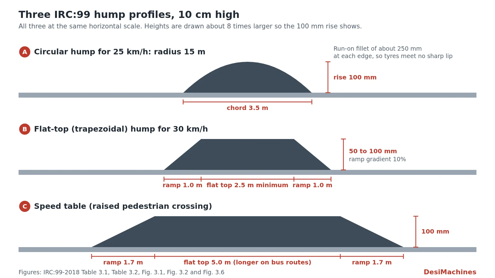
A speed breaker built to IRC:99-2018 for a 25 km/h crossing is a smooth circular hump 10 cm (100 mm) high and 3.5 m long along the road, shaped as part of a circle of 15 m radius. For faster crossing speeds the code keeps the same 10 cm rise and stretches the hump out, up to 9.5 m long with a 113 m radius at 50 km/h.
IRC:99 is the Indian Roads Congress guideline on slowing traffic down. Its 2018 edition, titled Guidelines for Traffic Calming Measures in Urban and Rural Areas, replaced the 1988 “tentative guidelines” on speed breakers. It covers two hump shapes, the raised crossing called a speed table, and gentler tools such as rumble strips and bar markings. This guide gives the tables, shows how to mark out the curve on site, and explains where a breaker is allowed and how it must be painted and signed.
What are the speed breaker dimensions as per IRC:99?
For a round-top (circular) hump, IRC:99-2018 fixes the height at 10 cm and changes the length to suit the speed you want drivers to cross at. Three words explain the table:
- Rise is the height of the hump at its centre, above the road surface.
- Chord length is how long the hump is along the road, from where it leaves the road surface to where it meets it again.
- Radius is the radius of the circle the curved top is cut from. A bigger radius means a flatter, longer hump that can be crossed faster.
Table 1: Circular hump dimensions by design speed (IRC:99-2018 Table 3.1, rise 10 cm)
| Speed you want cars to cross at | Radius | Chord length (along the road) | Speed a bus can cross at |
|---|---|---|---|
| 20 km/h | 11 m | 3.0 m | 5 km/h |
| 25 km/h | 15 m | 3.5 m | 10 km/h |
| 30 km/h | 20 m | 4.0 m | 15 km/h |
| 35 km/h | 31 m | 5.0 m | 20 km/h |
| 40 km/h | 53 m | 6.5 m | 25 km/h |
| 45 km/h | 80 m | 8.0 m | 30 km/h |
| 50 km/h | 113 m | 9.5 m | 35 km/h |
We checked every row with the circle formula given further down. Each pair of radius and chord gives a rise of 100 mm, give or take 3 mm.
The height matters more than anything else in the table. The code warns that a hump lower than 10 cm lets traffic cross faster than the listed speed, and a hump higher than 10 cm may damage vehicles. Buses and trucks have long wheelbases, so they feel the hump much more than a car does; the last column shows how slowly a bus must cross. Where buses must keep 40 km/h, IRC:99 asks for a radius of 180 m and a chord of 12 m.
Across the road, the 1988 edition said a breaker on an undivided road should always cover the whole carriageway, shoulders included. The 2018 code allows the hump to stop short at the edge so rainwater can still flow along the road, and the marking code recommends a short raised footpath beside it, so drivers cannot dodge the hump by using the shoulder.
Why do older drawings show 3.7 m width and 17 m radius?
Those numbers come from IRC:99-1988, the first edition. It gave one design for all roads: a rounded hump of 17 m radius, 3.7 m wide (measured along the road) and 0.10 m high, for a “preferred advisory crossing speed” of 25 km/h. They are still copied in old estimates, drawings and textbooks.
Table 2: The 1988 and 2018 editions compared for a 25 km/h hump
| Item | IRC:99-1988 | IRC:99-2018 |
|---|---|---|
| Title | Tentative guidelines on speed breakers on minor roads | Guidelines for traffic calming measures in urban and rural areas |
| Height | 0.10 m | 10 cm |
| Radius | 17 m | 15 m |
| Length along the road | 3.7 m | 3.5 m |
| Other speeds | One design only | 20 to 50 km/h, Table 1 |
| Heavy vehicles | 1.5 m ramps at 1 in 20 added at each edge | Bus speeds listed per design; speed table preferred on bus routes |
The height is the same, so the two humps feel much alike. The 2018 version for 25 km/h is a little shorter. For new work, quote IRC:99-2018 and check which edition the contract drawing names before you build.
What are the dimensions of a flat-top speed breaker?
A flat-top hump, which IRC:99 calls a trapezoidal hump, is a raised flat section of road 50 to 100 mm high with a sloping ramp on each side. The flat portion must be at least 2.5 m long. Because the top is flat, it can double as a pedestrian crossing. Cars cross it with moderate discomfort, while lorries and buses must go very slowly.
Table 3: Ramp length and gradient for a flat-top hump (IRC:99-2018 Table 3.2)
| Speed you want cars to cross at | Length of each ramp | Ramp gradient | Speed a bus can cross at |
|---|---|---|---|
| 20 km/h | 0.7 m | 14.0% | Not given |
| 25 km/h | 0.8 m | 12.5% | 5 km/h |
| 30 km/h | 1.0 m | 10.0% | 10 km/h |
| 35 km/h | 1.3 m | 7.5% | 15 km/h |
| 40 km/h | 1.7 m | 6.0% | 20 km/h |
| 45 km/h | 2.0 m | 5.0% | 25 km/h |
| 50 km/h | 2.5 m | 4.0% | 30 km/h |
Multiply any ramp length by its gradient and you get about 100 mm, the full height. So the faster the design speed, the longer and gentler the ramp. If buses must cross at 35 or 40 km/h, the ramps grow to 3.3 m at 3.0% and 4.0 m at 2.5%.
How big is a speed table?
A speed table is a raised pedestrian crossing: a long flat-top hump that runs across the full width of the road between the kerbs. In IRC:99-2018 (Fig. 3.6) it is 100 mm high, with 1.7 m ramps on each side and a 5.0 m flat top, so about 8.4 m long overall. The 1.7 m ramp works out to a gradient of about 6%, the same as the 40 km/h line of Table 3.
The code prefers a speed table to a hump on bus routes. On a road with many buses, the flat top should be made as long as a bus’s full wheelbase, so the bus never rocks over two slopes at once. The top should be built in a material that looks different from both the road and the footpath. Along highways that pass schools, hospitals and institutions, IRC:99 asks for raised crossings every 100 to 150 m, with “speed breaker ahead” and “school/hospital area” warning signs and a 30 km/h limit.
How do you mark out the curve of a circular hump?
You need two numbers from Table 1: the radius (R) and the rise (h, 100 mm). For a shallow hump like this, the rise, chord (c) and radius are linked by a simple formula:
h = c² ÷ (8 × R)
For the 25 km/h hump: 3.5 × 3.5 ÷ (8 × 15) = 12.25 ÷ 120 = 0.102 m, which is the 10 cm the code asks for.
To shape the hump, a site team needs the height at points along the chord. Table 4 gives them for the 25 km/h design, measured from the centre line of the hump outwards. Cut a timber or steel template to these heights and drag it across the hot material, or set the side forms to them.
Table 4: Set-out heights for a 25 km/h circular hump, radius 15 m (our arithmetic)
| Distance from centre of hump | Height above road |
|---|---|
| 0 (centre) | 100 mm |
| 250 mm | 98 mm |
| 500 mm | 92 mm |
| 750 mm | 81 mm |
| 1,000 mm | 67 mm |
| 1,250 mm | 48 mm |
| 1,500 mm | 25 mm |
| About 1,730 mm (edge) | 0 |
Notice how flat the top is: the first 500 mm from the centre drops only 8 mm. Most of the fall happens near the edges. A hump built with a peaked middle instead is a different, harsher hump from the one in the table. The code’s own drawing (Fig. 3.1, for the 40 km/h hump) also shows a short run-on fillet, about 250 mm, where the hump meets the road, so tyres do not hit a sharp lip.
The same geometry tells you how much material a hump takes. A shallow circular hump has a cross-section of about two-thirds of chord times rise: 2/3 × 3.46 m × 0.1 m ≈ 0.23 m² (our arithmetic). Across a 7 m two-lane road with 1.5 m shoulders on both sides, that is about 2.3 m³ of compacted mix for one hump.
Where are speed breakers allowed on Indian roads?
A speed breaker belongs on a minor road, not on a highway. Both editions of IRC:99 say this in their own way.
The 1988 edition said speed breakers are meant mainly for residential areas and minor roads, and that their use on major inter-city roads outside towns “is not considered a good engineering practice”. It listed where they make sense:
- the minor road at a T-junction with a fast rural highway, placed about 10 m from the inner edge of the main road
- residential streets, school, college and hospital campuses
- approaches to temporary diversions, narrow or weak bridges and culverts, railway level crossings and sharp curves with poor visibility
It also said a breaker should not be built on a bridge itself. Where a bridge is narrow, sits on a curve or has a crash record, each approach gets two breakers instead. Where breakers repeat along a stretch, they were spaced 100 to 120 m apart, centre to centre.
The 2018 edition goes further for highways. Where a national or state highway passes through a village, it says speed breakers “have not proven to be effective”, because each one slows traffic for only 70 to 80 m around it, and a badly built one can damage low cars at night. Instead it builds a speed zone: speed limit signs from 500 to 750 m out, rumble strips, and lower limits close in, down to 25 km/h within the village boundary for most vehicles (20 km/h for heavy vehicles). Where a village road meets a highway, the breakers go on the village road, to bring its traffic down to 30 km/h or less at the junction, while the highway gets rumble strips and warning signs. Near schools the code recommends a maximum of 25 km/h, and 30 km/h near hospitals. The guide to types of roads in India explains how national highways, state highways, district roads and village roads differ.
At a junction, a hump does not replace clear visibility. Drivers still need to see the crossing traffic, as set out in the guide to sight distance in highway design.
How should a speed breaker be painted and signed?
An unmarked hump is a hazard, especially at night. IRC:35-2015, the Indian Roads Congress code for road markings, sets out the paint (clause 11.1):
- Two rows of chequered marking on each sloping side, in alternate black and white squares of 500 mm.
- White triangular markings on both round-top and flat-top humps, with a 750 mm base and a height of up to 1,850 mm.
- Retro-reflective paint, which shines back in headlights, backed up with road studs.
Ahead of the hump, drivers need an advance warning sign. IRC:99-2018 uses “road hump ahead” and “speed breaker ahead” signs and refers to IRC:67, the road signs code, for their design. The 1988 edition placed the hump warning sign, with a “SPEED BREAKER” definition plate, 40 m before the first breaker.
Where traffic arrives fast, transverse bar markings can warn drivers before the hazard. IRC:35-2015 Table 11.1 sets how many sets to lay: one set at 50 m for approach speeds up to 50 km/h, two sets (50 and 80 m) for 51 to 65 km/h, three sets (50, 80 and 120 m) for 66 to 80 km/h, and four sets (adding one at 180 m) for 81 to 100 km/h. What thermoplastic marking paint costs is covered in our post on thermoplastic road marking paint price.
Upkeep is part of the design. The 1988 code calls repainting the most important maintenance job on a hump, along with clearing the mud and dust that collect on either side of it.
When are rumble strips or rubber speed bumps used instead?
A full hump is not always the right tool. IRC:99-2018 describes softer devices that warn drivers or slow them a little without a 10 cm jolt.
Table 5: Speed breaker and the softer alternatives in IRC:99-2018
| Device | Size | Where the code uses it |
|---|---|---|
| Speed breaker (circular or flat-top hump) | 10 cm high; 3.0 to 9.5 m long (circular); flat top at least 2.5 m | Minor roads, residential and local streets, minor arms of highway junctions; not on bus routes |
| Speed table | 100 mm high; 1.7 m ramps and 5.0 m flat top | Pedestrian crossings, bus routes, highways past schools and hospitals |
| Rumble strips | 20 to 30 mm high, 200 to 300 mm wide, about 1 m apart, roughly 6 strips per location | National and state highways and arterial roads, across the carriageway and paved shoulder |
| Transverse bar marking, 5 mm | Sets of 6 thermoplastic bars, 200 to 300 mm wide, 600 mm apart | A soft warning on the approach to a hazard |
| Transverse bar marking, 15 mm | Sets of 6 bars, 300 mm wide, 1,000 mm apart | Where speed must drop, with “SLOW” marked 20 m and 40 m before the bars |
| Precast speed bump (rubber or plastic) | Ready-made sections nailed to the road | Local and collector streets only |
Rumble strips are cast in place with cement concrete or bituminous premix. The 5 mm bars are laid in two coats of thermoplastic and the 15 mm bars in six, each coat put down at least an hour after the last has set; the 15 mm bars may be made of mastic asphalt instead.
The code is wary of the ready-made rubber and plastic bumps sold in the Indian market. On fast roads they become a hazard, and once traffic breaks them, the nails that held them stay on the road and damage tyres.
How is a bitumen speed breaker built on site?
The 1988 edition (clause 7) describes the hot-mix method, which a small crew can follow with a few forms and a load of premix:
- Mark the hump’s position on the road and cut grooves (indents) into the surface there, so the new material bonds.
- Sweep off all dust and loose material, then spray a tack coat, a thin layer of bitumen that acts as glue. The guide to prime coat and tack coat explains it.
- Set forms of the right height, shape and width, and pour hot premixed bituminous material into them.
- Lift the forms, shape the surface to the profile and round the edges with a trowel.
- Compact the material well, leaving extra height for what compaction takes out, and fix any high or low spots with fine bituminous mix or by scraping.
- Let it cure before opening the road to traffic, and mark it as described above.
Drainage needs planning too. A hump laid across a road can dam rainwater, and the code asks for arrangements so that no ponds or puddles form beside it. The road’s cross slope does most of this work; see the guide to camber in road construction.
A hump is a short, narrow strip, so a 9-tonne road roller is more machine than the job needs. A small tandem roller suits the job better, for example the Dynapac CC800 (1,575 kg operating weight, 800 mm drum), the CASE 450NX (2,900 kg, 1,000 mm drum) or the Dynapac CC125 CEV-V (2,800 kg, 1,200 mm drum). The mini roller guide explains how these small machines are used.
Laying humps, patches or village roads? Compare tandem roller models and talk to a dealer near your site.
Where the figures in this guide come from. Tables 1 and 3, the speed table and flat-top drawings, the rumble strip and bar marking sizes, the bus speeds and the highway rules are from IRC:99-2018, Guidelines for Traffic Calming Measures in Urban and Rural Areas, read from the printed pages and drawings. The 17 m, 3.7 m and 0.10 m design, the placement list, spacing, sign position and the building method are from IRC:99-1988, Tentative Guidelines on the Provision of Speed Breakers for Control of Vehicular Speeds on Minor Roads. Marking sizes and Table 11.1 are from IRC:35-2015, Code of Practice for Road Markings. Table 4, the formula check and the material quantity are our own arithmetic.
More on how roads are planned and built is in the road construction guides, and the guide to machinery required for road construction lists the full fleet a road job uses. When you are ready, compare road rollers and compactors and speak to a dealer near your site.
Prices, specifications and features are indicative, vary by variant, location and date, and should always be confirmed with the official OEM or authorised dealer before any purchase decision. DesiMachines is not liable for decisions taken on the basis of information that may have changed after publication.
Machines, tenders and news for this industry: Road Construction