
 Excavator
294 models
 Backhoe Loader
51 models
 Crane
68 models
 Concrete Mixer
79 models
 Wheel Loader
54 models
 Compactor / Roller
45 models
 Motor Grader
42 models

 Concrete Pump
66 models
 Skid Steer Loader
11 models


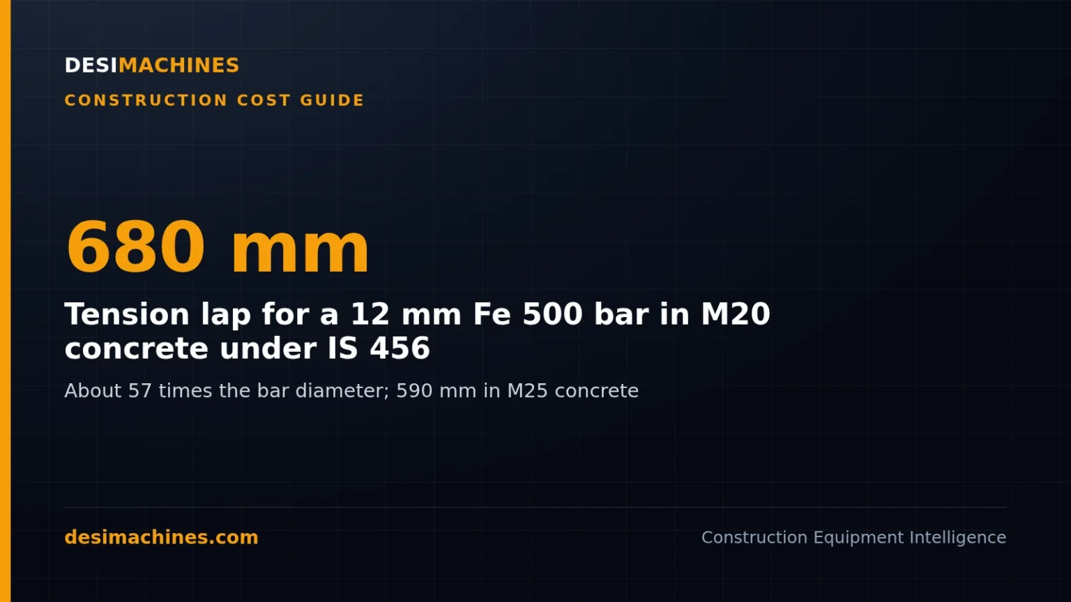
For Fe 500 TMT bars in M20 concrete, IS 456 needs a tension lap of about 57 times the bar diameter, which is 680 mm for a 12 mm bar. In M25 concrete the same lap falls to about 49 times the diameter, or 590 mm.
Lap length is the overlap you leave when one bar has to carry on from another. Development length is the length a bar needs inside concrete to pass its full force into it, and every lap length in the code is built from it. This guide gives the IS 456 formula, the bond stress values behind it, ready tables by bar size for M20 and M25, and the extra rules that apply in columns, beams and slabs.
What is development length?
Development length (Ld) is the length of bar that has to be embedded in concrete so that the grip between steel and concrete, called bond, can take up the full design force in the bar. Stop a bar short of that length and, at full load, it pulls out of the concrete before the steel itself gives way.
IS 456:2000, the Indian code for plain and reinforced concrete, gives it in clause 26.2.1:
Ld = φ × σs ÷ (4 × τbd)
Here φ is the bar diameter, σs is the stress in the bar at design load and τbd is the design bond stress. For a fully stressed bar in limit state design, σs is taken as 0.87 times the yield strength of the steel. That is 435 N/mm² for Fe 500 and 361 N/mm² for Fe 415.
The bond stress comes from clause 26.2.1.1. The code lists it for plain round bars and then raises it by 60 per cent for ribbed bars made to IS 1786, which is what a TMT bar is. Bars in compression get a further 25 per cent.
Table 1: Design bond stress τbd in N/mm² (IS 456:2000, clause 26.2.1.1)
| Concrete grade | Plain bars in tension | TMT (IS 1786) bars in tension | TMT bars in compression |
|---|---|---|---|
| M20 | 1.2 | 1.92 | 2.40 |
| M25 | 1.4 | 2.24 | 2.80 |
| M30 | 1.5 | 2.40 | 3.00 |
| M35 | 1.7 | 2.72 | 3.40 |
| M40 and above | 1.9 | 3.04 | 3.80 |
Two things follow. Ribs lock a TMT bar into the concrete, so it needs a shorter length than a plain bar to do the same work. And stronger concrete grips harder, so the length falls as the grade goes up.
A worked example, a 16 mm Fe 500 bar in M20 concrete:
- In tension: 16 × 435 ÷ (4 × 1.92) = 6,960 ÷ 7.68 = 906 mm. Write 910 mm on the drawing.
- In compression: 16 × 435 ÷ (4 × 2.40) = 6,960 ÷ 9.6 = 725 mm. Write 730 mm.
Where there is no room for the full straight length, such as at the end of a beam, a bend or hook can make up part of it. Clause 26.2.2.1 counts each 45 degree bend as 4φ, up to a maximum of 16φ, and a standard U-type hook as 16φ. For a bar in compression, clause 26.2.2.2 counts only the projected length of a bend or hook.
What is the difference between lap length and development length?
TMT bars are sold in fixed lengths, mostly 12 m. When a beam or slab needs a longer run, or a column carries on to the next floor, one bar is overlapped with the next and the force passes from bar to bar through the concrete between them. That overlap is the lap length, and the joint is called a lap splice.
Table 2: Development length and lap length compared
| Development length | Lap length | |
|---|---|---|
| Where it is used | Where one bar ends inside concrete: at supports, at cut-off points, into a footing | Where two bars overlap to act as one |
| What it does | Anchors one bar into the concrete | Passes the force from one bar to the next |
| IS 456 clause | 26.2.1 | 26.2.5.1 |
| How it is worked out | φ × σs ÷ (4 × τbd) | From Ld, with code minimums and multipliers |
Clause 26.2.5.1 turns the development length into a lap length in three cases:
- Flexural tension, the case in beams and slabs: Ld or 30φ, whichever is greater.
- Direct tension, as in a tie member: 2Ld or 30φ, whichever is greater.
- Compression, as in a column: the development length in compression, but not less than 24φ.
The straight part of any tension lap must also be at least 15φ or 200 mm, whichever is greater. For TMT bars in M20 to M30 concrete, Ld always works out above 30φ, so in ordinary beams and slabs the lap length is simply the development length.
Lap length table by bar diameter for M20 and M25
The table below applies those rules to Fe 500 and Fe 500D bars, the grades most houses and small buildings now use. Both grades have the same 500 N/mm² yield strength, so their laps are the same.
Table 3: Lap length for Fe 500 TMT bars, in mm (IS 456 clauses 26.2.1 and 26.2.5.1)
| Bar diameter | M20, tension lap | M25, tension lap | M20, compression lap | M25, compression lap |
|---|---|---|---|---|
| 8 mm | 460 | 390 | 370 | 320 |
| 10 mm | 570 | 490 | 460 | 390 |
| 12 mm | 680 | 590 | 550 | 470 |
| 16 mm | 910 | 780 | 730 | 630 |
| 20 mm | 1,140 | 980 | 910 | 780 |
| 25 mm | 1,420 | 1,220 | 1,140 | 980 |
| 32 mm | 1,820 | 1,560 | 1,450 | 1,250 |
These are our own arithmetic for fully stressed bars, rounded up to the next 10 mm. Before rounding they match the development length tables in SP 34, the BIS handbook on concrete reinforcement and detailing (Table 4.4 for Fe 500). The tension column is the flexural tension case. Multiply it where the section on longer laps below says so.
If your bars are Fe 415, or you want the figure for a size not listed, use the multiple of the diameter instead:
Table 4: Development length as a multiple of bar diameter (φ)
| Steel | M20 tension | M25 tension | M30 tension | M20 compression | M25 compression | M30 compression |
|---|---|---|---|---|---|---|
| Fe 415 | 47.0φ | 40.3φ | 37.6φ | 37.6φ | 32.2φ | 30.1φ |
| Fe 500 | 56.6φ | 48.5φ | 45.3φ | 45.3φ | 38.8φ | 36.3φ |
Is 50d lap length enough? If a drawing or a contractor gives one round figure such as 50d for every lap, check it against Table 4. For Fe 500 in M20, 50d is short of the 56.6φ the code works out in tension: a 12 mm bar lapped at 600 mm instead of 680 mm is under-lapped by 80 mm. In M25 the same 50d is a little more than the 48.5φ needed. The grade of concrete on site has to be the grade the lap was worked out for, which is what the cube test of concrete checks.
Once the steel is tied and checked, the pour comes next. Compare concrete mixer models and talk to a dealer about the size your slab or column work needs.
What is the lap length in a column?
A column bar is mainly in compression, so IS 456 lets its lap equal the development length in compression, with a floor of 24φ (clause 26.2.5.1 d). For Fe 500 in M20 that is 45.3φ: 550 mm for a 12 mm bar and 730 mm for a 16 mm bar.
That is the minimum, and two rules often make the column lap longer. Columns in a frame also bend under wind and earthquake loads, which puts one face in tension. IS 13920:2016, the code for detailing concrete buildings to resist earthquakes, is compulsory for the frames that resist sideways load in buildings in seismic zones III, IV and V, and optional in zone II. For column laps, its clause 7.3.2.1 asks for:
- a lap length not less than the tension development length of the largest bar, so 680 mm for 12 mm Fe 500 bars in M20, not 550 mm;
- laps only in the central half of the clear column height, never inside a beam-column joint or within 2d of the beam face (d is the depth of the member);
- closed links at a spacing of not more than 100 mm over the whole lap;
- no more than 50 per cent of the bar area lapped at any one section;
- no laps at all for bars larger than 32 mm, which are joined with mechanical couplers to IS 16172.
SP 34 (1987) shows the older non-seismic detail, where column bars start just above floor level over a short concrete kicker, about 75 mm high, that holds the column shutters. In zones III to V, IS 13920 moves the lap to the middle half of the column, where the bending from sideways loads is lowest. Where a column gets smaller from one floor to the next, SP 34 has the lower bars cranked inward at a slope of not more than 1 in 6, with extra ties at the bend.
Your structural drawing says which code the frame is detailed to. Follow the drawing, and ask the engineer if the lap position is not shown.
What is the lap length in a beam?
Beam bars are in flexural tension, so the lap is Ld or 30φ, whichever is greater. With TMT bars up to M30 that means Ld: 910 mm for a 16 mm Fe 500 bar in M20.
Where the lap sits matters as much as its length. Clause 26.2.5 asks for splices to be placed away from the sections of maximum stress and staggered. It recommends that in beams they are not placed where the bending moment is more than half of what the section can resist, and that not more than half the bars are spliced at one section. In a continuous beam the bottom bars carry their highest tension near mid-span and the top bars carry theirs over the supports. So bottom bars are lapped towards the supports and top bars around mid-span, each where its own tension is low.
In seismic zones, IS 13920 clause 6.2.6.1 adds its own limits for beams. No lap inside a joint, within 2d of the column face, or within a quarter of the beam length next to any point where the beam may yield in an earthquake. Closed stirrups at not more than 150 mm over the lap. A lap not less than the tension development length of the largest bar. And no more than 50 per cent of the top or bottom steel lapped at one section.
Plinth beams follow the same rules. The plinth beam cost guide shows how their steel and concrete are taken off.
What is the lap length in a slab?
Slab bars are in flexural tension too, so the same rule applies: Ld or 30φ, with the straight part of the lap at least 15φ or 200 mm. For bars of 12 mm and less, 15φ comes to 180 mm or under, so the 200 mm figure is the one that sets that minimum. In practice the full development length is longer anyway. With Fe 500 in M20, a 10 mm main bar needs 570 mm and an 8 mm bar 460 mm.
Watch the top bars. A slab’s top steel over the beams is a tension bar at the top of the section as cast. If its cover is less than twice the bar diameter, clause 26.2.5.1 c raises the lap by a factor of 1.4, as the next section shows.
Some slabs use ready-welded steel mesh (welded wire fabric) in place of loose bars. For mesh, clause 26.2.5.1 f sets a different lap: the overlap measured between the outermost cross wires must be at least the spacing of the cross wires plus 100 mm.
When does the lap length have to be increased?
Clause 26.2.5.1 lists the cases where the basic lap is not enough:
- A tension bar at the top of a section as cast, where the minimum cover is less than 2φ: multiply the lap by 1.4.
- A tension bar at a corner, where the cover to either face is less than 2φ, or where the clear gap between neighbouring laps is less than 75 mm or 6φ, whichever is greater: multiply by 1.4.
- Where both of the above apply: multiply by 2.0.
- Members in direct tension: 2Ld or 30φ, with the splice enclosed in spirals of at least 6 mm bar at a pitch of not more than 100 mm.
- Bars of two different sizes lapped together: work the lap out on the smaller bar.
- Bars larger than 36 mm: do not lap. Weld them, or where welding is not practicable, lap with extra spirals around the bars.
Bundled bars, two to four bars tied in contact, need more as well. Clause 26.2.1.2 raises the development length by 10 per cent for two bars, 20 per cent for three and 33 per cent for four, and laps in a bundle are made one bar at a time, staggered.
A worked example: a 12 mm Fe 500 top bar in an M20 slab with 20 mm cover. Twice the diameter is 24 mm, which is more than the 20 mm cover, so the top-bar factor applies. The lap becomes 680 × 1.4 = 952 mm. Call it 960 mm. Cover is held by cover blocks, and a thin cover changes the lap as well as the durability.
How far apart should laps be staggered?
Laps count as staggered when the centre-to-centre distance between neighbouring laps is at least 1.3 times the lap length (clause 26.2.5.1 b). For a 680 mm lap that is 1.3 × 680 = 884 mm, so the centres sit at least about 890 mm apart. Put two laps closer than that and the code treats them as being at the same section, which counts against the limit of half the bars spliced at one place.
Figure 1: Staggered laps in three neighbouring bars (12 mm Fe 500, M20, lap 680 mm)
Orange = the 680 mm lap zone in each bar. The lap centres step along by 1.3 × 680 = 884 mm or more, so no two laps share a section. Drawn to scale along the bar; bar spacing not to scale.
On site, CPWD Specifications 2009 (Volume 1, clause 5.3.1.1) add three working rules for government work. Lapped bars should not touch: keep them apart with concrete between them by 25 mm or 1¼ times the largest aggregate size, whichever is greater. Where that is not possible, tie the two bars together at intervals of not more than twice the bar diameter, with two strands of annealed wire. And never lap more than 50 per cent of the steel area at one section. The wire and its gauge are covered in the binding wire guide.
How much extra steel do laps add?
Every lap is a length of bar that does no work past the joint, and it is bought and paid for by weight. A run of bar longer than 12 m needs one lap for every bar after the first, and each 12 m bar only moves the run forward by 12 m less one lap. So on a long run, the steel spent in laps is about the lap length divided by (12 m minus the lap length).
Table 5: Steel spent in laps on long runs of 12 m Fe 500 bars in M20 (tension laps)
| Bar diameter | Lap length | Weight per metre | Steel in one lap | Extra steel on a long run |
|---|---|---|---|---|
| 12 mm | 680 mm | 0.889 kg | about 0.6 kg | about 6 per cent |
| 16 mm | 910 mm | 1.580 kg | about 1.4 kg | about 8 per cent |
| 20 mm | 1,140 mm | 2.469 kg | about 2.8 kg | about 10.5 per cent |
| 25 mm | 1,420 mm | 3.858 kg | about 5.5 kg | about 13 per cent |
Weights per metre are φ² ÷ 162; the rest is our own arithmetic. Short members such as house beams under 12 m have no lap in their main bars at all, so these figures apply to long beams, long slab runs and column bars carried up through floors. They show why laps belong on the bar bending schedule, where each one adds to the cutting length, and not as a loose allowance. On CPWD contracts only the laps shown on the drawing or approved by the engineer are paid; extra overlaps are not, as the material wastage guide explains.
How do you check laps on site before the pour?
- Measure each lap with a tape against the drawing or the remarks column of the bar bending schedule. A lap is measured from the end of one bar to the end of the other along the overlap.
- Check the grade of steel on the bar tags. A lap worked out for Fe 415 is too short for Fe 500. The TMT bar grades guide explains the markings.
- Count the laps at any one cross-section: not more than half the bars.
- Check the stagger: lap centres at least 1.3 times the lap length apart.
- In columns detailed to IS 13920, check that laps sit in the middle half of the clear height, with links at 100 mm or closer along them.
- Check the cover where two bars sit side by side at a lap. The extra bar must not push into the cover.
A lap that is short by a few centimetres cannot be fixed once the concrete is in. It is a two-minute check with a tape before the pour.
With the steel passed, the job moves to concrete. A self-loading mixer such as the CONMAT CSLM 2800 batches at site on a house or small building, and on bigger pours ready-mixed concrete arrives in a transit mixer such as the Schwing Stetter AM 7 (C2). Browse the full range of concrete mixers to match a machine to your pours. More estimating topics are in the construction cost guides.
The development length formula, bond stresses and lap rules on this page are from IS 456:2000, Plain and Reinforced Concrete, Code of Practice, clauses 26.2.1, 26.2.1.1, 26.2.1.2, 26.2.2.1, 26.2.2.2, 26.2.5 and 26.2.5.1. Seismic lap rules are from IS 13920:2016, Ductile Design and Detailing of Reinforced Concrete Structures Subjected to Seismic Forces, clauses 1.1.1, 6.2.6.1 and 7.3.2.1; its Amendments 1 (2017) and 2 (2020) do not change those lap clauses. The column detail and the development length tables are from SP 34:1987, Handbook on Concrete Reinforcement and Detailing, clause 7.3.1 and Tables 4.3 and 4.4. The site rules are from CPWD Specifications 2009, Volume 1, clause 5.3.1.1. Lap lengths in mm, rounding and steel percentages are our own arithmetic. All sources were read in October 2026.
Prices, specifications and features are indicative, vary by variant, location and date, and should always be confirmed with the official OEM or authorised dealer before any purchase decision. DesiMachines is not liable for decisions taken on the basis of information that may have changed after publication. Lap and development lengths for your building are set by your structural engineer’s design and drawings; this page explains the code rules and does not replace them.
Machines, tenders and news for this industry: Building Construction