
 Excavator
294 models
 Backhoe Loader
51 models
 Crane
68 models
 Concrete Mixer
79 models
 Wheel Loader
54 models
 Compactor / Roller
45 models
 Motor Grader
42 models

 Concrete Pump
66 models
 Skid Steer Loader
11 models


Layers no thicker than 250 mm after rolling, each one watered, compacted and tested before the next goes on: that is how a road embankment is raised in India under Section 305 of the MoRTH road specifications. Embankment construction in road work follows a fixed order. Clear and mark the land, firm up the ground, bring in approved soil, spread it, set its moisture, roll it, test it, and repeat until the bank reaches subgrade level. Then shape and cover the slopes.
A bank rolled in thick layers, or rolled dry, keeps settling after the road is built, and the road on top cracks with it.
What is an embankment in road construction?
An embankment is a raised bank of compacted earth that carries the road above the surrounding ground. It is built where the road crosses low land, a flood plain, a paddy field or the approach to a bridge. Where the road passes through high ground instead, the earth is dug away, and that is a cutting.
The top 500 mm of the bank is the subgrade, the layer the pavement rests on, and it is held to stricter rules than the earth below it. How the subgrade, sub-base, base and surface stack up is shown in our guide to road construction layers. The reason for the care is water: IRC:36-2010, the Indian Roads Congress code for earth embankments, says drainage must keep the bank from getting soaked up to 1 m below the top of the subgrade.
What are the steps of embankment construction?
There are ten steps, and the order matters. Each layer has to pass its test before the next goes on.
Table 1: Embankment construction steps, the rule behind each and the machine that does it
| Step | What is done | Rule | Usual machine |
|---|---|---|---|
| 1. Clear the site | Trees, roots, bushes and rubbish removed inside the marked limits | MoRTH 201; IRC:36 clause 7 | Dozer, backhoe loader |
| 2. Set out | Centre line marked; batter pegs fixed on both sides; bank built a little wider than the drawing | MoRTH 305.3.1 | Survey instruments |
| 3. Strip topsoil | Up to 150 mm removed and stockpiled no more than 2 m high for later use on slopes | MoRTH 305.3.3 | Dozer, motor grader, loader |
| 4. Prepare the ground | Standing water drained; ground levelled, loosened, watered and rolled; unsuitable soil dug out | MoRTH 305.3.2 and 305.3.4 | Pump, motor grader, soil compactor |
| 5. Bring in fill | Soil from the road’s own cuttings first, then from approved borrow areas | MoRTH 305.2.2 | Excavator, backhoe loader, tippers |
| 6. Spread the layer | Uniform layer over the full width, no thicker than 250 mm once compacted | MoRTH 305.3.5.1 | Motor grader |
| 7. Set the moisture | Water sprinkled and mixed in, or wet soil dried, to within 1% above and 2% below the optimum | MoRTH 305.3.5.2 | Water tanker, disc harrow |
| 8. Compact | Rolled to 95% of lab density in the embankment, 97% in the subgrade | MoRTH 305.3.6 and Table 300-2 | Single drum soil compactor, padfoot roller, pneumatic roller |
| 9. Test the layer | Field density checked and the layer approved before the next is placed | MoRTH 305.3.6 and 903.2.2 | Site laboratory |
| 10. Finish | Slopes trimmed and rounded off; topsoil spread; grass or turf planted | MoRTH 305.3.9 | Motor grader, excavator |
Steps 6 to 9 repeat for every layer. A 3 m high bank built in 250 mm layers goes through that loop twelve times.
How is the ground prepared before the first layer?
MoRTH treats the ground under the bank as its foundation. After clearing, the limits of the bank are marked with batter pegs, small stakes showing where each side slope will meet the ground. The bank is built slightly wider than the drawing so the loose edge can be trimmed off later. Standing water is pumped or bailed out. Topsoil is stripped no deeper than 150 mm and kept in heaps no higher than 2 m, because it goes back on the finished slopes.
The bare ground is then levelled, loosened, watered and rolled. Two rules decide how deep this goes:
- Where the finished subgrade will sit less than 0.5 m above the natural ground, and that ground is not already at 97% of lab density, it is dug loose to 0.5 m below subgrade level and recompacted in layers to 97%.
- Where the ground holds swamp soil, peat, organic matter or other unsuitable material, at least 500 mm of it is removed and replaced with approved fill.
On any natural slope steeper than 1 vertical to 4 horizontal, the ground is cut into steps, called benches, so the new fill locks into it instead of sliding. On wet slopes, MoRTH clause 305.4.2 asks for benches with a slight inward fall and a subsoil drain at the lowest point.
Where does the soil for an embankment come from?
The road itself comes first. Earth from cuttings and drains on the same stretch is used before anything is brought in, and the best of it is saved for the subgrade. Which soils pass and which do not, from black cotton clay to fly ash, is covered in our guide to road construction materials.
When that runs short, soil comes from borrow areas. MoRTH discourages borrow pits beside the road, and where the engineer allows them, they stay at least 10 m from the bank, no deeper than 1.5 m, and broken by a ridge at least 8 m wide every 300 m or less. On temporarily acquired farmland, IRC:36 clause 8.1.7 limits a pit to 1 m: strip 150 mm of topsoil, dig no more than a further 850 mm, then spread the topsoil back so the field can be farmed again. The state charges a fee on this soil, explained in our post on royalty on earthwork.
One more rule: soil may be hauled to the bank only when enough spreading and compaction plant is working there to handle it.
How thick should each embankment layer be?
No more than 250 mm after compaction when a vibratory roller does the rolling, and no more than 200 mm with an 80 to 100 kN static roller. That is MoRTH clause 305.3.5.1, and IRC:36 clause 8.3.1 sets the same 250 mm limit. Vibration drives the compacting effort deeper, which is why it earns the thicker layer.
The layer is spread over the full width with a motor grader, and MoRTH asks for a blade with hydraulic control so slope and level can be set and held. For a padfoot (sheepsfoot) roller, IRC:36 caps the loose layer at the length of the feet plus 50 mm. Before rolling:
- Clods are broken down to 75 mm in the embankment and 50 mm in the subgrade.
- Stones are ordinarily no bigger than 75 mm in the embankment and 50 mm in the subgrade, and never more than two-thirds of the compacted layer thickness.
The next layer waits until this one has passed its density test and been approved.
How much water should the soil have before rolling?
Within 1% above to 2% below its optimum moisture content, the water content at which that soil packs densest in the lab test (IS 2720 Part 8). Too dry, and the grains will not pack. Too wet, and the soil pumps under the drum.
Water is added from a tanker with a sprinkler that spreads it evenly, without flooding, then mixed through the layer by blading or with a disc harrow. IRC:36 also allows watering the borrow pit before digging. Soil that arrives too wet is spread to dry in the sun; if rain keeps it wet, compaction stops. Expansive clay is the exception: it is rolled on the wet side of its optimum. How moisture and density are checked on a rolled layer is explained in the field density test guide.
Which roller compacts an embankment, and how many passes does it need?
A self-propelled single drum vibratory roller or padfoot vibratory roller of 80 to 100 kN static weight, roughly 8 to 10 tonnes, or a heavy pneumatic tyre roller, says MoRTH clause 305.3.6. The same clause rules out two shortcuts: a dozer or loader does not count as compaction equipment, and light rolling done first to help a heavier machine is ignored.
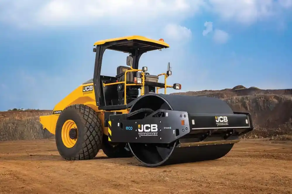
A single drum soil compactor (JCB VM117). The steel drum vibrates while the rubber-tyred rear drives the machine.
The number of passes is found on site, for each soil, with a trial. IRC:36 clause 20 describes it: a strip about 20 m long and 5 m wide is covered with 250 mm of loose soil at the right moisture, the roller makes 4, 6 and 8 passes (4, 8 and 16 for a sheepsfoot roller), and dry density is measured after each set, as the mean of five tests. The pass count that reaches the required density becomes the rule for that soil and machine. Clause 20.4 adds that counting passes never replaces testing. The required density is 95% of the lab maximum in the embankment and 97% in the subgrade. A spot that stays soft is dug out, refilled and compacted with a light roller, a walk-behind double drum roller or a plate compactor.
Of the 21 single drum soil compactors we list, 14 publish an operating weight between 10 and 12 tonnes, among them the L&T 1190 (11,050 kg), the Escorts EC 5250 (10,350 kg) and the JCB VM117 (11,525 kg), as published for each machine in November 2026. MoRTH’s 80 to 100 kN band is a guide to roller size, not a list of approved models; the site trial and the engineer’s approval settle which roller is used. Compare two of them in JCB VM117 vs L&T 1190. For sticky clay, a padfoot (sheepsfoot) roller kneads the soil better than a smooth drum, and the soil compactor guide explains drum, amplitude and frequency.
What side slope should a road embankment have?
Between 1.5 horizontal to 1 vertical and 2H:1V where the bank stays dry, and between 2H:1V and 3H:1V where it may stand in floodwater. That is IRC:36 clause 5.2, which says these slopes are recommended mainly for traffic safety.
A slope of 2H:1V means the bank spreads 2 m outwards for every 1 m it rises, so the slope decides how much land the bank takes. The table is our own arithmetic for a bank with a 12 m wide top.
Table 2: How side slope changes the base width of a 12 m wide embankment
| Bank height | Base width at 1.5H:1V | Base width at 2H:1V | Base width at 3H:1V |
|---|---|---|---|
| 1 m | 15 m | 16 m | 18 m |
| 2 m | 18 m | 20 m | 24 m |
| 3 m | 21 m | 24 m | 30 m |
| 4 m | 24 m | 28 m | 36 m |
Base width = top width + 2 x (slope ratio x height). A 3 m bank at 3H:1V needs a strip 30 m wide, two and a half times its own top.
Where land is too costly for flat slopes, IRC:36 clause 5.3 allows steeper ones if the slope is mechanically stabilised and safety measures such as crash barriers are added. Once trimmed, MoRTH asks for the slope face to be sealed, usually by running a tracked machine up and down it.
How do you widen an existing road embankment?
By cutting steps into the old slope first. MoRTH clause 305.4.1 asks for continuous horizontal benches at least 300 mm wide wherever the old slope is steeper than 1 vertical to 4 horizontal; a flatter slope only needs ploughing or scarifying. A strip too narrow for a full-size roller is compacted with a light vibratory roller, a walk-behind double drum roller, a vibratory plate compactor or a tamper, and soil should not be tipped straight off a truck into it unless nothing else fits.
When a new bank goes over an old road, clause 305.4.3 gives three cases:
- A granular road surface within 1 m of the new formation level is scarified about 50 mm deep, and the top 500 mm below the new subgrade is compacted to the required density.
- A bitumen or concrete surface within 1 m of the new level is removed completely.
- An old surface more than 1 m below the new level is only roughened, provided at least 500 mm of subgrade sits above it.
What changes for high banks, soft ground and bridge approaches?
A bank over 6 m high is a design job. IRC:36 says such banks are designed under IRC:75, with boreholes at least twice as deep as the bank is high. MoRTH adds that they normally use fly ash or approved borrow soil, may be raised in stages with instruments watching settlement, and may carry extra fill (a surcharge) for a set period before the road is built. Fly ash banks need a soil cover at least 500 mm thick on the sides, and IRC:36 puts at least 500 mm of earth on top as subgrade.
Where the ground cannot carry loaded tippers and rollers, MoRTH clause 305.4.5 lets the first layer be built by dumping loads side by side until it is thick enough to work on, and a geotextile or geogrid may be laid first to spread the load. Fill placed in standing water must be non-plastic gravel, sand or rock with no particle over 75 mm and a uniformity coefficient of at least 10, tipped in from the end of the bank without compaction. Waterlogged and marshy ground follows IRC:34.
Around culverts and bridges, fill within twice the road height from the back of an abutment is placed separately from the main bank. No soil goes against a wall until the concrete or masonry has stood 14 days, and the fill rises in equal layers on both sides. The backfill must not be organic soil or a clay with a plasticity index above 20 or liquid limit above 40.
How is an embankment protected from rain and erosion?
During construction, the top of each layer is kept at a crossfall steep enough to shed water, the same idea as the finished road’s cross slope in the camber guide. A layer damaged by rain is dug out, refilled and recompacted with a small roller, plate compactor or rammer before work moves on.
A bank also settles a little after it is finished, so IRC:36 clause 19.1 sets the finished level 1 to 2 per cent of the bank height above the design level. On a 4 m bank that is 40 to 80 mm (our arithmetic). The rule does not apply to high approaches to bridges, where closer compaction control keeps settlement small.
The topsoil saved at the start is spread back over the slopes 75 to 150 mm thick, after the slope face is roughened and dampened so it sticks. Grass or turf is then planted (MoRTH clauses 307 and 308), and the top and bottom of each slope are rounded off into the land around it. Where a high bank is built of sandy soil, IRC:36 suggests a blanket of cohesive soil over the sandy core.
Which machines are used for embankment construction?
Six jobs, each with its own machine.
Table 3: Machines for embankment construction in road work
| Job | Machine | What it does on the bank |
|---|---|---|
| Clearing and stripping | Dozer, backhoe loader | Pushes off vegetation and topsoil, pulls stumps |
| Digging fill | Excavator, backhoe loader | Loads borrow soil or cutting spoil into tippers |
| Hauling | Tippers and dumpers | Carry soil from cutting or borrow area to the bank |
| Spreading | Motor grader | Spreads each layer to an even thickness and cross slope; trims slopes |
| Watering and mixing | Water tanker, tractor with disc harrow | Brings soil to optimum moisture and mixes it through |
| Rolling | Soil compactor, padfoot roller, pneumatic tyre roller | Compacts each layer to 95% (embankment) or 97% (subgrade) |
| Narrow strips and repairs | Plate compactor, walk-behind roller, rammer | Widening strips, abutment backfill, soft spots |
On a highway job the borrow pit is usually worked by a 20-tonne excavator such as the Tata Hitachi EX 210 Infra. On a village road, a JCB 3DX backhoe loader often clears, digs and loads on the same day. The grader sets the pace, because nothing is rolled until a layer is spread; see how motor graders work. For how many of each machine a road package needs, see the guide to machinery required for road construction.
Planning an embankment job? Compare soil compactors by weight and drum size and speak to a dealer near your site.
How is embankment earthwork measured?
In cubic metres, from cross-sections taken after clearing and again after the bank is finished. MoRTH clause 305.8.1 uses the average end area method: the average of two neighbouring cross-section areas times the distance between them. Borrow soil is paid as the compacted fill minus the suitable soil from the road’s own cuttings, counting one cubic metre from a cutting as one cubic metre of fill and ignoring bulking and shrinkage.
The bank sits under the pavement, so read next how the CBR test decides how thick the road layers above it must be. More on how roads are built is in the road construction guides, and the full range of road rollers and compactors is there when the site is ready.
Where the figures in this guide come from. Construction rules, layer thicknesses, moisture limits, roller types, borrow pit limits, widening, special conditions and measurement are from Section 305 of the MoRTH Specifications for Road and Bridge Works (fifth revision). Side slopes, the compaction trial, settlement allowance, farmland borrow pits and high-bank investigation are from IRC:36-2010, Recommended Practice for Construction of Earth Embankments and Sub-grade for Road Works, checked against the printed pages. Roller weights are as published for each machine at the time of writing. Table 2, the twelve-layer count and the settlement example are our own arithmetic.
Prices, specifications and features are indicative, vary by variant, location and date, and should always be confirmed with the official OEM or authorised dealer before any purchase decision. DesiMachines is not liable for decisions taken on the basis of information that may have changed after publication.
Machines, tenders and news for this industry: Road Construction