
 Excavator
294 models
 Backhoe Loader
51 models
 Crane
68 models
 Concrete Mixer
79 models
 Wheel Loader
54 models
 Compactor / Roller
45 models
 Motor Grader
42 models

 Concrete Pump
66 models
 Skid Steer Loader
11 models


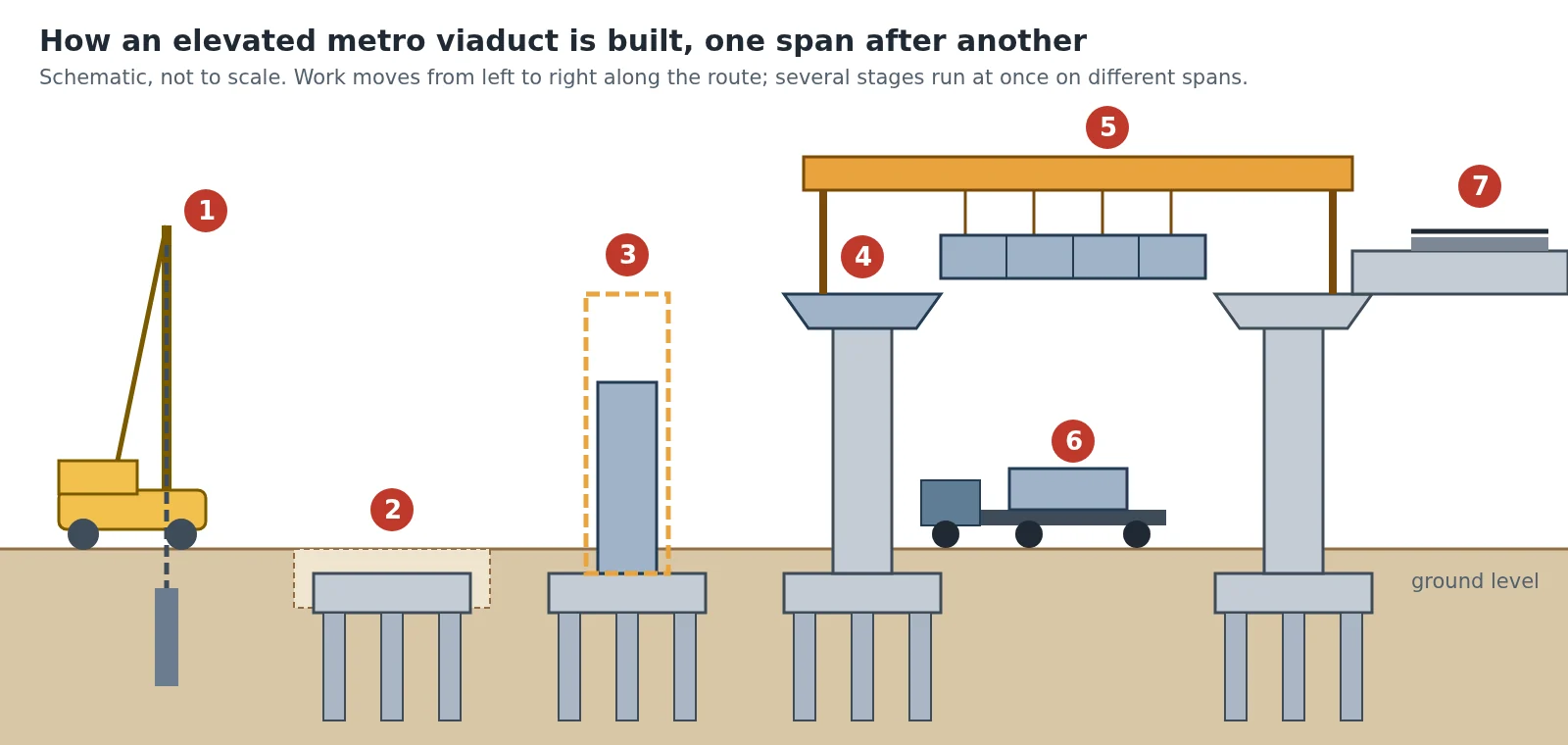
Six steps, repeated pier after pier, build an elevated metro line in India: bore the piles, cast the pile cap, raise the pier, top it with a pier cap, lift the deck on from above and lay the track. Stations go up as separate structures along the way. On the designs in Gujarat Metro’s project reports the piers stand 25 to 28 metres (about 82 to 92 feet) apart, so at 25 m a 10 km stretch of viaduct needs about 400 of them.
The work does not finish one pier before starting the next. Piling rigs work far ahead, pier gangs follow, and the deck crew comes last, so on a busy road you can see several stages at once. This guide walks through the metro construction process in that order, says which machine does each job, and ends with what it means for someone who owns or hires out machines. The figures come from two Detailed Project Reports (DPRs) and an environmental study for the Surat and Ahmedabad metros, named at the end. Underground lines are covered in a short section of their own.
What is the metro construction process, step by step?
The metro construction process has six steps that repeat at every pier, plus the stations, and the road is prepared before any of them. The Surat DPR says the central two lanes and the median are taken for the work, a strip about 9 m wide is barricaded during piling and foundation work, and two lanes are kept open for traffic on each side, widening the road if needed. It puts the time for this preparation, together with moving pipes and cables out of the way, at about 4 to 6 months.
Then the line is built in this order, with the stations built alongside:
- Piles. Deep concrete columns are bored into the ground at each pier position.
- Pile cap. A thick concrete block is cast on top of the group of piles to tie them together.
- Pier. A single round concrete column rises from the pile cap. People call it the metro pillar.
- Pier cap. A wider head is cast on top of the pier to carry the bearings that the deck sits on.
- Deck. Concrete pieces made in a casting yard are trucked in and lifted onto the piers, one span at a time.
- Track. Concrete plinths and rails are laid on the finished deck.
- Stations. Station structures are built at their own locations, and the deck work skips past them.
The table puts the steps beside the machines each one needs. The heaviest machines here are hired with a specialist crew; the rest are the same machines a road or building job uses.
| Step | What happens | Main machines |
|---|---|---|
| Road preparation | Barricading, moving pipes and cables, traffic diversion | Backhoe loaders, excavators, tippers |
| Piles | Bored cast-in-situ piles, 1.0 m or 1.2 m wide | Rotary piling rig, crane for the steel cage, transit mixers |
| Pile cap | Pit dug, piles cut to level, block cast | Excavator, pick-and-carry crane, transit mixers, concrete pump |
| Pier and pier cap | Steel formwork, reinforcement, concrete in lifts | Crane, transit mixers, concrete pump |
| Deck | Segments or whole girders brought in and lifted on | Low-bed or multi-axle trailers, launching girder, or two mobile cranes of 300 tonnes or more |
| Track | Concrete plinths, fastenings, rails | Transit mixers, small cranes, track machines |
| Stations | Columns, concourse and platform levels, roof | Cranes, concrete pumps, transit mixers |
How are metro pillars built?
A metro pillar is built from the bottom up in three parts: a group of piles below ground, a pile cap that joins them, and the round pier above. Piles carry the load down to firmer ground; for Surat, the DPR calls bored piles the most feasible foundation for the soil found along the route, with open foundations where the ground allows.
Piles. Both Gujarat DPRs propose bored cast-in-situ piles of 1.0 m and 1.2 m diameter, cut off 2 m below the existing ground level. The Surat report lists pile lengths of 24 to 26 m; the Ahmedabad Phase-II report gives effective depths of 20 to 30 m. Bored cast-in-situ means the hole is drilled first and the concrete is placed in it on site, as opposed to a pile made in a factory and hammered in. A rotary piling rig drills the hole, a crane lowers the steel reinforcement cage into it, and concrete from transit mixers is placed through a pipe from the bottom up. Where the ground turns to rock part-way down, the rig changes tools for the rock socket, which is explained in DTH piling vs rotary piling.
Pile cap. Once the piles are done, an excavator opens a shallow pit around their heads, the tops are broken down to the cut-off level, and a thick reinforced block is cast over the whole group. The cap spreads the weight of one pier onto all its piles.
Pier. The Surat report describes a single cast-in-place pier of 1.8 m to 2.0 m diameter, round for most of its height so that it takes up as little of the road median as possible. A jersey-shaped crash barrier 1.0 m high protects its base from traffic. The pier is usually cast inside steel formwork, with concrete pumped up from transit mixers parked alongside.
How tall is it? That depends on what the line has to clear. The Surat report keeps 5.5 m of clear height for road traffic under the deck and puts the minimum height of rail above the road at 8.4 m (about 28 feet); the Ahmedabad report says about 8.5 m. Where the line crosses a flyover or a railway, the piers get much taller.
Pier cap. The top of the pier widens into a pier cap that carries the bearings. In the Surat design the bearings sit about 1.8 m apart along the line and about 3.2 m across it, with room between them for the jack used when a bearing is replaced.
How is the metro deck made and lifted onto the piers?
The deck is not cast in the air. It is made on the ground in a casting yard, carried to the site on trailers and lifted onto the pier caps. The DPRs describe two ways to do it.
Segmental box girder with a launching girder. Each span is made of short concrete segments. The Surat report uses a 25 m standard span with segments 3.0 m long (2.0 m for the diaphragm segments that sit over the piers), and expects the heaviest segments to weigh about 50 tonnes. Segments are match cast, which means each one is cast against the face of the one before, so the joints fit exactly on site.
A launching girder is a long steel truss, slightly longer than two spans in the Surat design, that rests on the pier caps. Low-bed trailers bring the segments to the point of erection one at a time. A gantry running along the launching girder lifts each segment and hangs it in place until the whole span is hanging. The segments are then dry fitted, glued with epoxy and pulled together by steel cables that are tensioned from one end. The finished span is lowered onto its bearings and the launching girder moves forward to the next span. Because all of this happens above the road, the report notes that only a narrow strip of road is needed for the deck work.
Whole girders lifted by two cranes. The other method casts each span as one or two long U-shaped girders. The Ahmedabad Phase-II report uses a 28 m standard span, going up to 35 m with an extended pier cap, and switches to I-girders on sharp curves of less than 300 m radius. The girders are cured with water for 14 days in the yard, carried to the site on hydraulic multi-axle trailers and lifted on by two mobile cranes, each of not less than 300 tonnes capacity, working one at each end. The Surat report adds that this lifting is done at night without stopping traffic.
Spans longer than about 31 m (Surat) or 35 m (Ahmedabad), used at major crossings such as big junctions or existing bridges, are built differently: either as steel girders or by balanced cantilever, where the deck is built outwards from a pier in both directions at once until the two halves meet. Read how the big lifting machines on these jobs work in the guide to crawler cranes.
The casting yard is a factory of its own. The Surat report puts it at about 3.0 to 3.5 hectares per yard, with casting beds, curing and stacking areas, a batching plant with aggregate and cement storage, a site testing laboratory and a reinforcement yard.
Looking for cranes and concrete machines for this kind of job? Compare cranes, including hydras such as the Escorts Hydra 15 (15 tonnes maximum lifting capacity, as listed in November 2026), and concrete mixers, then speak to a dealer near your site.
How is the track laid on a metro viaduct?
Metro track on a viaduct sits on concrete, not on stone ballast. The Surat report proposes plinth-type ballastless track: rows of concrete plinths cast on the deck, with concrete derailment guards built into them, and the rails fixed to the plinths with base plates spaced 60 cm apart. The Ahmedabad report proposes the same. In tunnels the base plates are 70 cm apart on a concrete slab.
The two tracks on a box girder sit 4.2 m apart, centre to centre, in the Surat design, on a girder about 4.0 m wide at the bottom.
How are elevated metro stations built?
An elevated station is built as a separate structure, and the deck work skips over it. The Surat report says a station needs its own structural layout, which may mean a break in the launching operations at every station. The viaduct column usually stands on the median or footpath, with other columns on either side of the road carrying the concourse, which is the ticket hall floor that sits above the road and below the platforms.
Station work uses the same machines as a multi-storey building: cranes for steel and formwork, concrete pumps for the slabs and transit mixers feeding them. The guide to equipment used in high-rise building construction covers which machine reaches which height.
How is an underground metro built?
Underground lines are dug by a tunnel boring machine (TBM) between stations, and the stations themselves are usually built from the surface down. For Surat, the DPR proposes TBMs that can bore in soft soil and leave a tunnel with a finished internal diameter of at least 5.6 m, at least 6.0 m below the surface. The tunnel is lined as the TBM moves with rings of precast concrete pieces. Each ring is five segments plus a key piece, and each segment weighs about 3 tonnes.
The underground stations are built by cut and cover. The report lists the steps:
- Move the pipes and cables out of the way.
- Build support walls along both sides of the station box.
- Dig out the soil between the walls, fitting steel struts across to hold them apart.
- Build the station structure inside and remove the temporary struts.
- Backfill over the roof and restore the road.
Besides TBM tunnels and cut and cover, the Surat DPR also names NATM, a method that digs the tunnel in short lengths and supports it at once with sprayed concrete. The Surat environmental study lists the machines whose noise it modelled for construction: pile drivers, air compressors, backhoe loaders, concrete mixer trucks, concrete pumps, mobile cranes, dump trucks, jackhammers and generators. Read more about tunnelling machines and bridges in the page on bridge and tunnel construction equipment.
Which of these machines can a machine owner supply?
The biggest machines on a metro are specialist kit: piling rigs, launching girders, 300-tonne cranes, TBMs and track machines. These usually belong to the main contractor or its specialist subcontractors, or are hired in with their crews. The everyday machines around them are a different story, and they are needed from the first barricade to the last station slab.
- Road preparation and utility shifting keeps backhoe loaders such as the JCB 3DX and 20-tonne class excavators like the Tata Hitachi EX 210 Infra (20,300 kg operating weight, as listed) busy for months, along with tippers to carry the soil away.
- Pile caps need an excavator for the pit and a crane for cages and formwork.
- Every pile, pile cap, pier and pier cap is concrete, so transit mixers such as the Sunbeam 85 (8 m³ nominal filling capacity, as listed) and stationary pumps such as the Schwing Stetter SP 3000 are on site from the first pile to the last station slab. How to size a pump for the job is in the guide to concrete pumps.
- Pick-and-carry cranes move steel, formwork and small precast pieces around the yard and the work front. Some are sold in piling versions, such as the ACE FP 210 Piling (20 tonnes maximum lifting capacity, as listed).
Machine hire on these jobs is usually arranged by the main contractor or its subcontractors. Who builds track, bridges and stations is listed in railway contractors in India, and live metro packages appear on the tenders and opportunities desk. Machine classes, the models buyers ask about and the companies on this work are kept together on the page for railway and metro construction equipment. For other projects broken down by machine, see the heavy equipment guides.
Where the figures in this guide come from. Spans, segments, piles, piers, erection methods, track, road preparation and the underground method are from Gujarat Metro Rail Corporation’s Detailed Project Report for the Surat Metro Rail Project (December 2018, chapter 5) and the Detailed Project Report for the Ahmedabad Phase-II Metro Rail Corridor (March 2019). The machine list is from Table 5.5 of the EIA Study for Surat Metro Rail Project Phase-I (RITES, December 2020). Both DPRs describe their designs as preliminary, so a built line can differ. Machine capacities are from the listed specifications in November 2026.
Prices, specifications and features are indicative, vary by variant, location and date, and should always be confirmed with the official OEM or authorised dealer before any purchase decision. DesiMachines is not liable for decisions taken on the basis of information that may have changed after publication.