
 Excavator
294 models
 Backhoe Loader
51 models
 Crane
68 models
 Concrete Mixer
79 models
 Wheel Loader
54 models
 Compactor / Roller
45 models
 Motor Grader
42 models

 Concrete Pump
66 models
 Skid Steer Loader
11 models


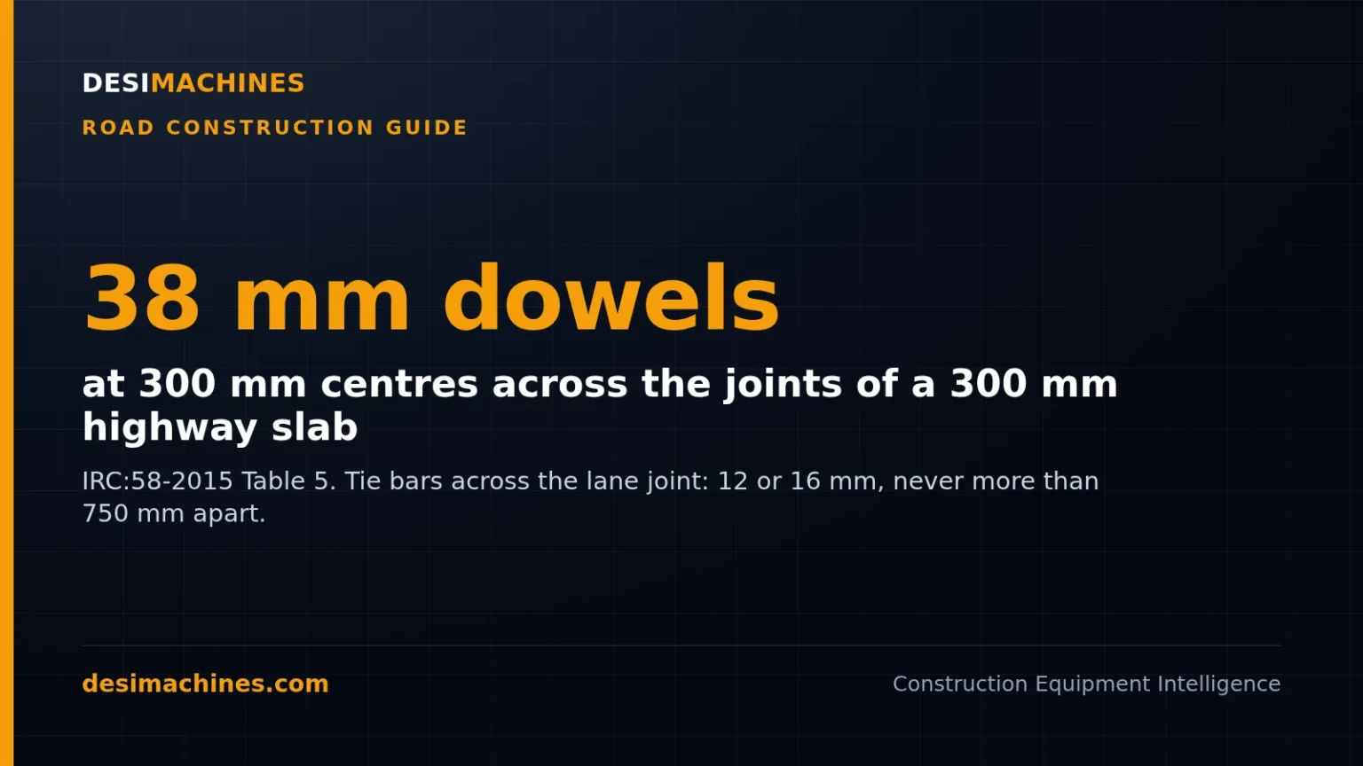
Dowel bars and tie bars are the two kinds of steel that cross the joints of a concrete road, and they do opposite jobs. A dowel bar is a smooth round bar laid along the line of traffic across a transverse joint, so the weight of a loaded wheel passes from one slab to the next while both slabs stay free to shrink and grow; a tie bar is a ribbed bar laid across the longitudinal joint between lanes to hold the slabs together, and it is not meant to carry load at all.
On a 300 mm highway slab, the Indian Roads Congress design code IRC:58-2015 recommends 38 mm dowels at 300 mm centres, and the construction code IRC:15-2017 says no dowel may be shorter than 500 mm. The tie bars on that same road are 12 or 16 mm.
Get the steel wrong and the road tells you within a few monsoons. The slabs start to step at the joints, and every truck bangs over them.
What is the difference between dowel bars and tie bars?
A concrete road, called rigid pavement or PQC (pavement quality concrete) on a highway job, is cut into panels. On a highway a panel is usually 3.5 m wide (one lane) and no more than 4.5 m long. The cuts across the road are transverse joints. The cut that runs along the road, between two lanes or between a lane and a concrete shoulder, is the longitudinal joint. The two bars belong to different joints, and the code treats them as different things.
Table 1: Dowel bar and tie bar compared (IRC:58-2015 and IRC:15-2017)
| Point | Dowel bar | Tie bar |
|---|---|---|
| Joint it crosses | Transverse joints: contraction, construction and expansion | Longitudinal joints, and the joint with a tied concrete shoulder |
| Job | Carries wheel load from one slab to the next, so the joint cannot step (fault) | Holds two slabs together so the joint cannot open; not a load transfer device |
| Movement | Must let the slabs slide apart and back along its length | Must not slide; it is bonded on both sides |
| Steel | Plain mild steel round bar, IS 432 Grade I | Deformed (ribbed) TMT bar, Fe 500 to IS 1786 |
| Typical size | 25 to 38 mm diameter, 500 mm minimum length | 8 to 16 mm diameter (16 mm maximum), 440 to 800 mm long |
| Spacing | 300 mm centre to centre, first bar 150 mm from the edge | 320 to 660 mm for plain bars and 510 to 1,060 mm for ribbed bars in the code’s table, never more than 750 mm apart |
| Treatment | Anti-corrosion coating, plus a thin plastic sheath over at least 60% of its length so one end can slide | Anti-corrosion coating, plus bituminous paint for 75 mm each side of the joint |
| Position | Mid-depth of the slab, plus or minus 25 mm, parallel to the road surface and centre line | Middle third of the slab depth, at least 30 mm below the bottom of the joint groove |
The short way to remember it: the dowel lets the slabs move but keeps them level, and the tie keeps the slabs together but does not let them move.
One word of warning on search results. In buildings, “dowel bars” means the starter bars that run from a footing into a column, which are lapped and bonded like normal reinforcement. That is a different thing. The lap length guide covers how those bars are joined. This page is about roads only.
Why are dowel bars provided in rigid pavement?
A loaded truck wheel reaching a joint pushes the edge of the first slab down. With nothing across the joint, the next slab gets none of that load, and the edge bends alone. Over thousands of axles, the slab on the leaving side settles lower than the slab behind it. Engineers call that faulting, and it is the bump you feel at every joint on a tired concrete road.
IRC:58 clause 7.2.1 says load is transferred across transverse joints “by means of mild steel round dowel bars”, and that dowels keep the ride smooth by preventing faulting. Clause 7.2.6 sets the trigger. Where traffic is heavier than 450 commercial vehicles per day (CVPD), dowels must be provided at contraction joints, because the grip between the broken stone faces of a sawn joint, called aggregate interlock, cannot be relied on under repeated heavy axles.
What actually fails is the concrete around the bar. Clause 7.2.2 says it is only the bearing stress, the pressure the bar puts on the concrete under it, that decides how long a dowel works. Too much bearing stress crushes the concrete around the bar, the bar works loose, and the joint starts to fault anyway. That is why the code says larger diameter dowels perform better: a fatter bar spreads the same load over more concrete.
One dowel does not carry the wheel alone. The bar right under the wheel takes the most, and its neighbours take less and less with distance. In the code’s worked design (Appendix VIII), a 330 mm slab with dowels at 300 mm spacing has four dowels sharing the load of a wheel near the edge. The same example puts the allowable bearing stress on M40 concrete with a 38 mm dowel at 26.7 MPa.
Figure 1: Section through a dowelled contraction joint (not to scale)
The dark strip at the top is the saw cut, sealed later; the slab cracks straight down from it. The dowel sits at mid-depth, with about 60% of its length sheathed so the slab on that side can slide. The sheath stops just past the joint. Base layer details are in the DLC guide.
What is the size, length and spacing of dowel bars as per IRC:58?
IRC:58-2015 Table 5 ties dowel size to slab thickness. Spacing stays at 300 mm all the way through; the bar gets thicker as the slab does.
Table 2: Recommended dowel bars by slab thickness (IRC:58-2015 Table 5, read with IRC:15-2017 clause 8.3.7)
| Slab thickness | Dowel diameter | Length in IRC:58 Table 5 | Minimum length under IRC:15-2017 | Spacing |
|---|---|---|---|---|
| 200 mm | 25 mm | 360 mm | 500 mm | 300 mm |
| 230 mm | 30 mm | 400 mm | 500 mm | 300 mm |
| 250 mm | 32 mm | 450 mm | 500 mm | 300 mm |
| 280 mm | 36 mm | 450 mm | 500 mm | 300 mm |
| 300 mm | 38 mm | 500 mm | 500 mm | 300 mm |
| 350 mm | 38 mm | 500 mm | 500 mm | 300 mm |
Two codes, two length columns, and the reason matters on site. IRC:58 Table 5 is a design guide, and its own note calls the values “general guidance”. IRC:15-2017 is the construction code, and clause 8.3.7 sets a minimum dowel length of 500 mm “keeping in view the requirement of load transfer and placement errors”. A dowel that lands 50 mm off the joint still needs enough bar on each side to work, so the later construction code asks for the longer bar. Diameter and spacing still come from IRC:58.
Three more rules travel with the table:
- No dowels in slabs thinner than 200 mm. The Table 5 note says dowels “shall not be provided” there, and IRC:15 clause 8.3.2.2 says the same for expansion joints, citing IS 6509.
- The first dowel sits 150 mm from the pavement edge, as in the code’s worked example and its drawing of the dowel support chair.
- A designer may add dowels under the wheel paths of heavy vehicles (clause 7.2.1). That is a judgement call from traffic, not a default.
Village roads are designed under a different code, IRC:SP:62, where low-volume contraction joints carry no dowels at all. The CC road construction guide covers that case, including the expansion-joint dowels a village road still needs next to a culvert.
What are the size, length and spacing of tie bars in rigid pavement?
Tie bars only have to stop two lanes drifting apart. The force they resist is friction: when the slab shrinks, it drags on the base below it. So the steel needed per metre of joint depends on the lane width, the slab weight and the friction, and not on traffic. IRC:58 Table 6 gives the result for a two-lane road with 3.5 m lanes, and clause 8.2.5 says the same details work for a tied concrete shoulder.
Table 3: Tie bars at the longitudinal joint, 3.5 m lane (IRC:58-2015 Table 6)
| Slab thickness | Tie bar diameter | Max spacing, plain bar | Max spacing, ribbed bar | Min length, plain bar | Min length, ribbed bar |
|---|---|---|---|---|---|
| 150 mm | 8 mm | 330 mm | 530 mm | 440 mm | 480 mm |
| 150 mm | 10 mm | 520 mm | 830 mm | 510 mm | 560 mm |
| 200 mm | 10 mm | 390 mm | 620 mm | 510 mm | 560 mm |
| 200 mm | 12 mm | 560 mm | 900 mm | 580 mm | 640 mm |
| 250 mm | 12 mm | 450 mm | 720 mm | 580 mm | 640 mm |
| 300 mm | 12 mm | 370 mm | 600 mm | 580 mm | 640 mm |
| 300 mm | 16 mm | 660 mm | 1,060 mm | 720 mm | 800 mm |
| 350 mm | 12 mm | 320 mm | 510 mm | 580 mm | 640 mm |
| 350 mm | 16 mm | 570 mm | 910 mm | 720 mm | 800 mm |
Read the spacing columns together with clause 8.2.4, which says tie bars “should not be spaced more than 750 mm apart” to avoid concentrating stress, and limits the diameter to 16 mm so the joint can still warp a little. Where the table gives 830, 900, 910 or 1,060 mm, the 750 mm limit is the one to build to. The same clause adds 50 to 80 mm to the calculated length to allow for placement error.
The table is built on allowable steel stresses of 125 MPa for plain bars and 200 MPa for deformed bars, and bond stresses of 1.75 and 2.46 MPa. That is why a ribbed bar can sit further apart and still hold: it grips the concrete harder and can be worked harder. Note the table applies to a 3.5 m lane. A carriageway cut into two 5 m halves, which IRC:15 also allows, needs the calculation redone for the wider slab.
On placement, IRC:15 clause 8.4.6 keeps tie bars in the middle third of the slab depth and below the saw cut, with each bar centred on the joint line within 50 mm and at least 30 mm of concrete between the bar and the bottom of the joint groove.
Why is a dowel bar plain and a tie bar ribbed?
Because one has to slide and the other must not. IRC:15-2017 clause 3.5 asks for dowel bars in plain mild steel to IS 432 Grade I, and tie bars in Fe 500 TMT steel to IS 1786. A ribbed TMT bar locks into concrete; that grip is the whole point in a column or a tie bar, and the opposite of what a dowel needs. The TMT bar guide explains Fe 500 and how the ribs grip.
A plain bar is not enough on its own to let a dowel slide, so the code adds a debonding sheath. Clause 8.3.9 asks for a thin plastic sheath, no more than 0.5 mm thick on average and closed at the end, over at least 60% of the bar’s length at contraction joints. At expansion joints, the sheath covers half the length plus 50 mm. The sheathed bar has to pass a pull-out test (clause 8.3.10): four bars cast into concrete blocks of 150 x 150 x 600 mm, pulled at seven days, must move 0.25 mm at an average bond stress of no more than 0.14 MPa. In plain words, the bar should slide out with almost no resistance.
Expansion joints, which IRC:58 clause 7.1.4 now keeps only next to bridges and culverts, need more room. Each dowel there gets a closed-end cap 100 mm long, of GI pipe or stiff plastic 2 mm thick, over its sheathed end, with compressible sponge inside so the bar has space to move in at least as long as the joint filler board is thick (clause 8.3.11). That cap is what people search for as a “dowel bar cap”.
Then rust. Both bars are coated against corrosion to IS 13620 (clause 3.5), and IRC:58 clause 7.2.1 notes that coated dowels are often used in coastal and high-rainfall areas, with zinc, lead-based paint or epoxy coatings. IRC:15 clause 8.3.6 adds the site detail: the bar is cleaned by sand or shot blasting, coated within four hours of cleaning, protected from scratches during handling, and touched up wherever the coating is damaged. Tie bars also get bituminous paint for 75 mm on each side of the joint (clause 8.4.4), the stretch nearest the crack where water gets in. If calcium chloride is used to speed up setting, both bars must be coated (clause 12.19.3).
How are dowel bars and tie bars placed on a concrete road?
There are two ways, and the paver decides which.
On a mechanised highway job, the slip form paver carries a dowel bar inserter, or DBI. IRC:15 clause 10.1.12.1 says the paver “shall have” one. The DBI pushes each dowel down into the fresh concrete at the planned joint and vibrates the concrete closed over it. A tie bar inserter does the same for the longitudinal joint, from the top or the side. The way the paver works through a full lane is set out step by step in the slip form paving guide.
Where there is no DBI, dowels go into steel cradles, also called chairs or baskets, fixed to the base before the concrete arrives (clause 8.3.6). The cradle holds every bar at mid-depth and parallel. Tie bars in semi-mechanised work are made into rigid assemblies the same way (clause 8.4.5). When a single lane is laid against side forms, the code allows tie bars to be bent so half lies along the form, then straightened with a hollow GI pipe after the form is stripped.
At the end of a day’s work, or any time concreting stops for more than 30 minutes, a construction joint is formed against a steel bulkhead with holes drilled for the dowels (clauses 8.3.2.2 and 8.3.4). The bulkhead is oiled so it does not bond to the slab, staked square to the centre line, and shaped to the road’s camber.
Two habits on site do the most damage. A needle vibrator run against a dowel shakes it out of line, so clause 8.1 forbids the vibrator touching the bar. And a joint saw cut in the wrong place leaves the dowels sitting off the crack, so the code advises marking the dowel and tie bar positions on the edge of the DLC before paving, where the saw crew can see them.
Table 4: Alignment tolerances for dowel bars (IRC:15-2017 clauses 8.3.8 and 11.5.2)
| Check | Limit |
|---|---|
| Horizontal or vertical rotation (bar tilted or skewed) | Less than 10 mm over 500 mm of bar |
| Longitudinal shift (bar not centred on the joint) | Less than 50 mm |
| Depth | Mid-depth of the slab, plus or minus 25 mm |
| Rejection | Any bar more than 38 mm out; or more than half the bars at a joint outside any limit |
Need concrete hauled to a paving or culvert job? Compare transit mixer models by drum size and talk to a dealer near your site.
How is dowel bar alignment checked?
With a magnet, more or less. IRC:15-2017 asks for alignment to be checked with a magnetic pulse induction (MPI) scanner, a scanner run along the joint that locates each steel bar inside the hardened concrete and reports its depth, side shift and tilt, to the American standard ASTM E3013. Clause 10.1.12.1 says it can check a joint within a few hours of paving.
The checking rate is set out plainly:
- In the trial length laid before the main work, every transverse joint is scanned (clause 11.5.2).
- In normal work, the engineer reads the MPI report for every joint at the start and, once satisfied, drops to 25% of joints (clauses 10.1.12.1 and 11.5.5.1).
- Tie bar positions are checked with the same device (clause 11.5.4).
A joint where more than half the dowels miss any limit is treated as a locked joint and rejected (clause 11.5.5.2), and so is a joint with any bar more than 38 mm out. Rejected joints are rebuilt by full-depth repair under IRC:SP:83.
Where no scanner is on site, the code falls back on digging. The dowels are exposed in a 1 m width of fresh concrete across the slab; or, at the end of a day, the slab is run 2 m past the last joint and that extra length is broken out after the concrete sets, exposing half of each dowel to be measured (clause 11.5.5.3). The engineer can also drill a few cores above the dowels to look for honeycombing, the air pockets left when concrete is not compacted around the bar.
What happens if dowel bars are misaligned or left out?
A dowel that is tilted or skewed cannot slide. When the slab tries to shrink on a cold night, the bar holds it, the joint “locks”, and the slab cracks somewhere else. That is why the code’s rejection rule speaks of locked joints. A dowel shifted along the road leaves too little bar on one side of the crack to carry the load, which is the reason IRC:15 asks for 500 mm bars.
Leave the dowels out of a heavy road and the joint faults instead. IRC:58 clause 7.2.6 says the grip between the broken stone faces of the crack cannot be relied on under repeated heavy axles, so the leaving slab settles and the step grows with every season of loaded trucks.
On existing roads, the repair for poor load transfer is a dowel bar retrofit: slots are cut across the joint or crack and new dowels are set in them to restore load transfer. IRC:SP:83-2018 puts it with full-depth repair and cross-stitching, ahead of diamond grinding and resealing. The types of pavement failure guide shows how faulting, corner breaks and joint spalling are told apart and fixed. A concrete overlay on an old bitumen road uses its own, much shorter panels and lighter joint steel, covered in the whitetopping guide.
Which machines are used on a dowelled concrete road?
The joint steel is placed by the paving train, not by hand, on any highway job. In order of work:
- A slip form paver with a dowel bar inserter and tie bar inserter. Pavers are not a listed machine class on DesiMachines.
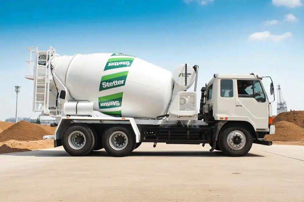
- Transit mixers or tippers bring the PQC from the batching plant to the paver. Listed transit mixers include the Schwing Stetter AM 6 (C2), the AJAX AF 7XE and the Putzmeister P10 PTO.
- Concrete saws cut the joints a few hours after laying, over the marked dowel and tie bar lines.
- An MPI scanner checks the bars once the concrete has set.
Figure 2: A transit mixer of the kind that carries paving concrete from the batching plant
How these machines fit into a full road package, from earthwork to surfacing, is set out in the guide to machinery required for road construction. Steel and other materials for each road layer, with the IS code each must pass, are listed in the road construction materials guide, and more on how roads are built is in the road construction guides.
Planning a concrete road or a widening job? Browse the full range of transit mixers and connect with a dealer near your site.
Where the figures in this guide come from. Dowel and tie bar sizes, the 450 CVPD trigger, the bearing-stress reasoning and the worked dowel example are from IRC:58-2015, Guidelines for the Design of Plain Jointed Rigid Pavements for Highways (fourth revision), clauses 6.2.5, 7.1, 7.2 and 8, Tables 5 and 6 and Appendices VIII and IX. Steel grades, the 500 mm minimum length, sheathing, caps, coating, placement and alignment checks are from IRC:15-2017, Code of Practice for Construction of Jointed Plain Concrete Pavements (fifth revision), clauses 3.5, 8.1 to 8.4, 10.1.12 and 11.5 to 11.7. Both were read in full from the published text. We cross-checked the tie bar spacings in Table 3 against the code’s own formula, and they match.
Prices, specifications and features are indicative, vary by variant, location and date, and should always be confirmed with the official OEM or authorised dealer before any purchase decision. DesiMachines is not liable for decisions taken on the basis of information that may have changed after publication.
Machines, tenders and news for this industry: Road Construction